![]()
|
|
||
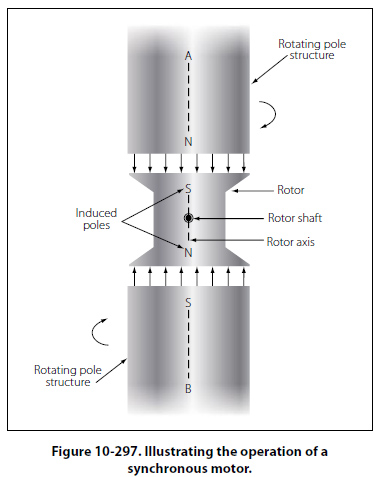
Synchronous Motor The synchronous motor is one of the principal types of AC motors. Like the induction motor, the synchronous motor makes use of a rotating magnetic field. Unlike the induction motor, however, the torque developed does not depend on the induction of currents in the rotor. Briefly, the principle of operation of the synchronous motor is as follows: A multiphase source of AC is applied to the stator windings, and a rotating magnetic field is produced. A direct current is applied to the rotor winding, and another magnetic field is produced. The synchronous motor is so designed and constructed that these two fields react to each other in such a manner that the rotor is dragged along and rotates at the same speed as the rotating magnetic field produced by the stator windings. An understanding of the operation of the synchronous motor can be obtained by considering the simple motor of Figure 10-297. Assume that poles A and B are being rotated clockwise by some mechanical means in order to produce a rotating magnetic field, they induce poles of opposite polarity in the soft iron rotor, and forces of attraction exist between corresponding north and south poles.
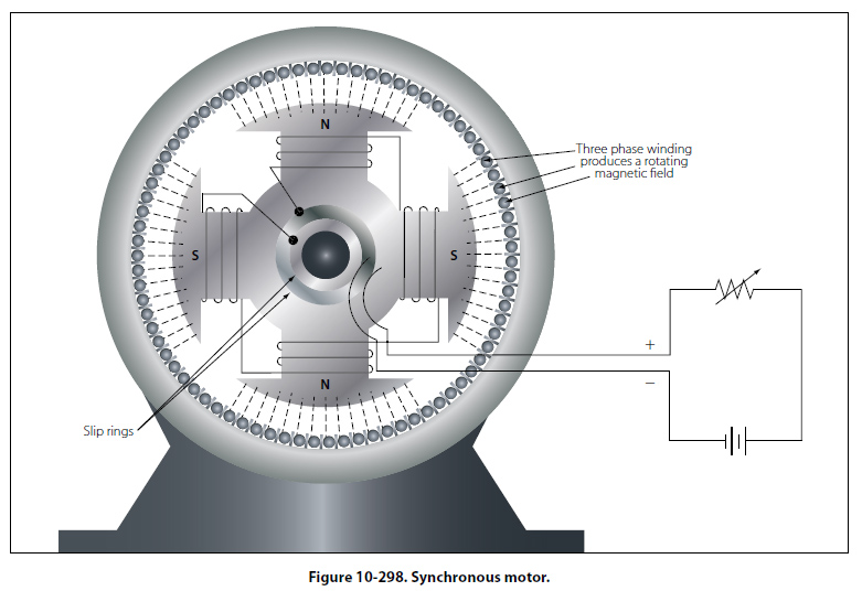
Consequently, as poles A and B rotate, the rotor is dragged along at the same speed. However, if a load is applied to the rotor shaft, the rotor axis will momentarily fall behind that of the rotating field but, thereafter, will continue to rotate with the field at the same speed, as long as the load remains constant. If the load is too large, the rotor will pull out of synchronism with the rotating field and, as a result, will no longer rotate with the field at the same speed. Thus the motor is said to be overloaded. Such a simple motor as that shown in Figure 10-297 is never used. The idea of using some mechanical means of rotating the poles is impractical because another motor would be required to perform this work. Also, such an arrangement is unnecessary because a rotating magnetic field can be produced electrically by using phased AC voltages. In this respect, the synchronous motor is similar to the induction motor. The synchronous motor consists of a stator field winding similar to that of an induction motor. The stator winding produces a rotating magnetic field. The rotor may be a permanent magnet, as in small single phase synchronous motors used for clocks and other small precision equipment, or it may be an electromagnet, energized from a DC source of power and fed through slip rings into the rotor field coils, as in an alternator. In fact, an alternator may be operated either as an alternator or a synchronous motor. Since a synchronous motor has little starting torque, some means must be provided to bring it up to synchronous speed. The most common method is to start the motor at no load, allow it to reach full speed, and then energize the magnetic field. The magnetic field of the rotor locks with the magnetic field of the stator and the motor operates at synchronous speed. The magnitude of the induced poles in the rotor shown in Figure 10-298 is so small that sufficient torque cannot be developed for most practical loads. To avoid such a limitation on motor operation, a winding is placed on the rotor and energized with DC. A rheostat placed in series with the DC source provides the operator of the machine with a means of varying the strength of the rotor poles, thus placing the motor under control for varying loads.
The synchronous motor is not a self-starting motor. The rotor is heavy and, from a dead stop, it is impossible to bring the rotor into magnetic lock with the rotating magnetic field. For this reason, all synchronous motors have some kind of starting device. One type of simple starter is another motor, either AC or DC, which brings the rotor up to approximately 90 percent of its synchronous speed. The starting motor is then disconnected, and the rotor locks in step with the rotating field. Another starting method is a second winding of the squirrel cage type on the rotor. This induction winding brings the rotor almost to synchronous speed, and when the DC is connected to the rotor windings, the rotor pulls into step with the field. The latter method is the more commonly used. |
| ©AvStop Online Magazine Contact Us Return To Books |