![]()
|
|
||
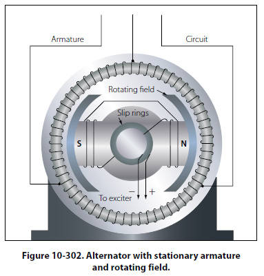
Number of Phases Another method of classification is by the number of phases of output voltage. Alternating current generators may be single phase, two phase, three phase, or even six phase and more. In the electrical systems of aircraft, the three phase alternator is by far the most common. Armature or Field Rotation Still another means of classification is by the type of stator and rotor used. From this standpoint, there are two types of alternators: the revolving armature type and the revolving field type. The revolving armature alternator is similar in construction to the DC generator, in that the armature rotates through a stationary magnetic field. The revolving armature alternator is found only in alternators of low power rating and generally is not used. In the DC generator, the emf generated in the armature windings is converted into a unidirectional voltage (DC) by means of the commutator. In the revolving armature type of alternator, the generated AC voltage is applied unchanged to the load by means of slip rings and brushes. The revolving field type of alternator has a stationary armature winding (stator) and a rotating field winding (rotor). [Figure 10-302] The advantage of having a stationary armature winding is that the armature can be connected directly to the load without having sliding contacts in the load circuit. A rotating armature would require slip rings and brushes to conduct the load current from the armature to the external circuit. Slip rings have a relatively short service life and arc over is a continual hazard; therefore, high voltage alternators are usually of the stationary armature, rotating field type. The voltage and current supplied to the rotating field are relatively small, and slip rings and brushes for this circuit are adequate. The direct connection to the armature circuit makes possible the use of large cross-section conductors, adequately insulated for high voltage. Since the rotating field alternator is used almost universally in aircraft systems, this type will be explained in detail, as a single phase, two phase, and three phase alternator.
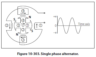
Single Phase Alternator Since the emf induced in the armature of a generator is alternating, the same sort of winding can be used on an alternator as on a DC generator. This type of alternator is known as a single phase alternator, but since the power delivered by a single phase circuit is pulsating, this type of circuit is objectionable in many applications. A single phase alternator has a stator made up of a number of windings in series, forming a single circuit in which an output voltage is generated. Figure 10-303 illustrates a schematic diagram of a single phase alternator having four poles. The stator has four polar groups evenly spaced around the stator frame. The rotor has four poles, with adjacent poles of opposite polarity. As the rotor revolves, AC voltages are induced in the stator windings. Since one rotor pole is in the same position relative to a stator winding as any other rotor pole, all stator polar groups are cut by equal numbers of magnetic lines of force at any time.
As a result, the voltages induced in all the windings have the same amplitude, or value, at any given instant. The four stator windings are connected to each other so that the AC voltages are in phase, or “series adding." Assume that rotor pole 1, a south pole, induces a voltage in the direction indicated by the arrow in stator winding 1. Since rotor pole 2 is a north pole, it will induce a voltage in the opposite direction in stator coil 2 with respect to that in coil 1. For the two induced voltages to be in series addition, the two coils are connected as shown in the diagram. Applying the same reasoning, the voltage induced in stator coil 3 (clockwise rotation of the field) is the same direction (counterclockwise) as the voltage induced in coil 1. Similarly, the direction of the voltage induced in winding 4 is opposite to the direction of the voltage induced in coil 1. All four stator coil groups are connected in series so that the voltages induced in each winding add to give a total voltage that is four times the voltage in any one winding. |
| ©AvStop Online Magazine Contact Us Return To Books |