![]()
|
|
||
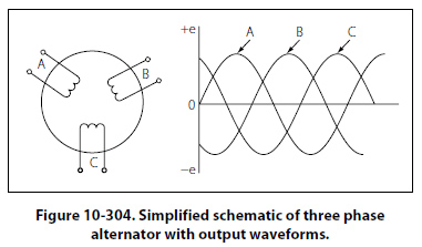
Two Phase Alternator Two phase alternators have two or more single phase windings spaced symmetrically around the stator. In a two phase alternator, there are two single phase windings spaced physically so that the AC voltage induced in one is 90° out of phase with the voltage induced in the other. The windings are electrically separate from each other. When one winding is being cut by maximum flux, the other is being cut by no flux. This condition establishes a 90° relation between the two phases. Three Phase Alternator A three phase, or polyphase circuit, is used in most aircraft alternators, instead of a single or two phase alternator. The three phase alternator has three single phase windings spaced so that the voltage induced in each winding is 120° out of phase with the voltages in the other two windings. A schematic diagram of a three phase stator showing all the coils becomes complex and difficult to see what is actually happening. A simplified schematic diagram, showing each of three phases, is illustrated in Figure 10-304. The rotor is omitted for simplicity. The waveforms of voltage are shown to the right of the schematic. The three voltages are 120° apart and are similar to the voltages which would be generated by three single phase alternators whose voltages are out of phase by angles of 120°. The three phases are independent of each other.
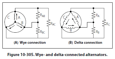
Wye Connection (Three Phase) Rather than have six leads from the three phase alternator, one of the leads from each phase may be connected to form a common junction. The stator is then called wye or star connected. The common lead may or may not be brought out of the alternator. If it is brought out, it is called the neutral lead. The simplified schematic (Figure 10-305A) shows a wye-connected stator with the common lead not brought out. Each load is connected across two phases in series. Thus, RAB is connected across phases A and B in series; RAC is connected across phases A and C in series; and RBC is connected across phases B and C in series. Therefore, the voltage across each load is larger than the voltage across a single phase. The total voltage, or line voltage, across any two phases is the vector sum of the individual phase voltages. For balanced conditions, the line voltage is 1.73 times the phase voltage. Since there is only one path for current in a line wire and the phase to which it is connected, the line current is equal to the phase current.
Delta Connection (Three Phase) A three phase stator can also be connected so that the phases are connected end to end as shown in Figure 10-305B. This arrangement is called a delta connection. In a delta connection, the voltages are equal to the phase voltages; the line currents are equal to the vector sum of the phase currents; and the line current is equal to 1.73 times the phase current, when the loads are balanced. For equal loads (equal output), the delta connection supplies increased line current at a value of line voltage equal to phase voltage, and the wye connection supplies increased line voltage at a value of line current equal to phase current. |
| ©AvStop Online Magazine Contact Us Return To Books |