![]()
|
|
||
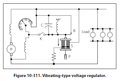
Regulation of Generator Voltage Efficient operation of electrical equipment in an airplane depends on a constant voltage supply from the generator. Among the factors, which determine the voltage output of a generator, only one, the strength of the field current, can be conveniently controlled. To illustrate this control, refer to the diagram in Figure 10-310, showing a simple generator with a rheostat in the field circuit. If the rheostat is set to increase the resistance in the field circuit, less current flows through the field winding and the strength of the magnetic field in which the armature rotates decreases. Consequently, the voltage output of the generator decreases. If the resistance in the field circuit is decreased with the rheostat, more current flows through the field windings, the magnetic field becomes stronger, and the generator produces a greater voltage. Voltage Regulation with a Vibrating-Type Regulator Refer to Figure 10-311. With the generator running at normal speed and switch K open, the field rheostat is adjusted so that the terminal voltage is about 60 percent of normal. Solenoid S is weak and contact B is held closed by the spring. When K is closed, a short circuit is placed across the field rheostat. This action causes the field current to increase and the terminal voltage to rise.
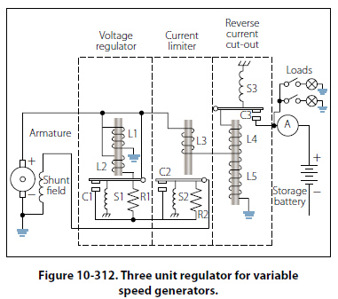
When the terminal voltage rises above a certain critical value, the solenoid downward pull exceeds the spring tension and contact B opens, thus reinserting the field rheostat in the field circuit and reducing the field current and terminal voltage. When the terminal voltage falls below a certain critical voltage, the solenoid armature contact B is closed again by the spring, the field rheostat is now shorted, and the terminal voltage starts to rise. The cycle repeats with a rapid, continuous action. Thus, an average voltage is maintained with or without load change. The dashpot P provides smoother operation by acting as a damper to prevent hunting. The capacitor C across contact B eliminates sparking. Added load causes the field rheostat to be shorted for a longer period of time and, thus, the solenoid armature vibrates more slowly. If the load is reduced and the terminal voltage rises, the armature vibrates more rapidly and the regulator holds the terminal voltage to a steady value for any change in load, from no load to full load, on the generator. Vibrating-type regulators cannot be used with generators, which require a high field current, since the contacts will pit, or burn. Heavy-duty generator systems require a different type of regulator, such as the carbon pile voltage regulator. Three Unit Regulators Many light aircraft employ a three unit regulator for their generator systems. This type of regulator includes a current limiter and a reverse current cutout in addition to a voltage regulator. The action of the voltage regulator unit is similar to the vibrating-type regulator described earlier. The second of the three units is a current regulator to limit the output current of the generator. The third unit is a reverse current cutout that disconnects the battery from the generator. If the battery is not disconnected, it will discharge through the generator armature when the generator voltage falls below that of the battery, thus driving the generator as a motor. This action is called “motoring" the generator and, unless it is prevented, it will discharge the battery in a short time. The operation of a three unit regulator is described in the following paragraphs. [Figure 10-312]
The action of vibrating contact C1 in the voltage regulator unit causes an intermittent short circuit between points R1 and L2. When the generator is not operating, spring S1 holds C1 closed; C2 is also closed by S2. The shunt field is connected directly across the armature. When the generator is started, its terminal voltage will rise as the generator comes up to speed, and the armature will supply the field with current through closed contacts C2 and C1. As the terminal voltage rises, the current flow through L1 increases and the iron core becomes more strongly magnetized. At a certain speed and voltage, when the magnetic attraction on the movable arm becomes strong enough to overcome the tension of spring S1, contact points C1 are separated. The field current now flows through R1 and L2. Because resistance is added to the field circuit, the field is momentarily weakened and the rise in terminal voltage is checked. Also, since the L2 winding is opposed to the L1 winding, the magnetic pull of L1 against S1 is partially neutralized, and spring S1 closes contact C1. Therefore, R1 and L2 are again shorted out of the circuit, and the field current again increases; the output voltage increases, and C1 is opened because of the action of L1. The cycle is rapid and occurs many times per second. The terminal voltage of the generator varies slightly, but rapidly, above and below an average value determined by the tension of spring S1, which may be adjusted. The purpose of the vibrator-type current limiter is to limit the output current of the generator automatically to its maximum rated value in order to protect the generator. As shown in Figure 10-312, L3 is in series with the main line and load. Thus, the amount of current flowing in the line determines when C2 will be opened and R2 placed in series with the generator field. By contrast, the voltage regulator is actuated by line voltage, whereas the current limiter is actuated by line current. Spring S2 holds contact C2 closed until the current through the main line and L3 exceeds a certain value, as determined by the tension of spring S2, and causes C2 to be opened. The increase in current is due to an increase in load. This action inserts R2 into the field circuit of the generator and decreases the field current and the generated voltage. When the generated voltage is decreased, the generator current is reduced. The core of L3 is partly demagnetized and the spring closes the contact points. This causes the generator voltage and current to rise until the current reaches a value sufficient to start the cycle again. A certain minimum value of load current is necessary to cause the current limiter to vibrate. The purpose of the reverse current cutout relay is to automatically disconnect the battery from the generator when the generator voltage is less than the battery voltage. If this device were not used in the generator circuit, the battery would discharge through the generator. This would tend to make the generator operate as a motor, but because the generator is coupled to the engine, it could not rotate such a heavy load. Under this condition, the generator windings may be severely damaged by excessive current. There are two windings, L4 and L5, on the soft iron core. The current winding, L4, consisting of a few turns of heavy wire, is in series with the line and carries the entire line current. The voltage winding, L5, consisting of a large number of turns of fine wire, is shunted across the generator terminals. When the generator is not operating, the contacts, C3 are held open by the spring S3. As the generator voltage builds up, L5 magnetizes the iron core. When the current (as a result of the generated voltage) produces sufficient magnetism in the iron core, contact C3 is closed, as shown. The battery then receives a charging current. The coil spring, S3, is so adjusted that the voltage winding will not close the contact points until the voltage of the generator is in excess of the normal voltage of the battery. The charging current passing through L4 aids the current in L5 to hold the contacts tightly closed. Unlike C1 and C2, contact C3 does not vibrate. When the generator slows down or, for any other cause, the generator voltage decreases to a certain value below that of the battery, the current reverses through L4 and the ampere turns of L4 oppose those of L5. Thus, a momentary discharge current from the battery reduces the magnetism of the core and C3 is opened, preventing the battery from discharging into the generator and motoring it. C3 will not close again until the generator terminal voltage exceeds that of the battery by a predetermined value. |
| ©AvStop Online Magazine Contact Us Return To Books |