![]()
|
|
||
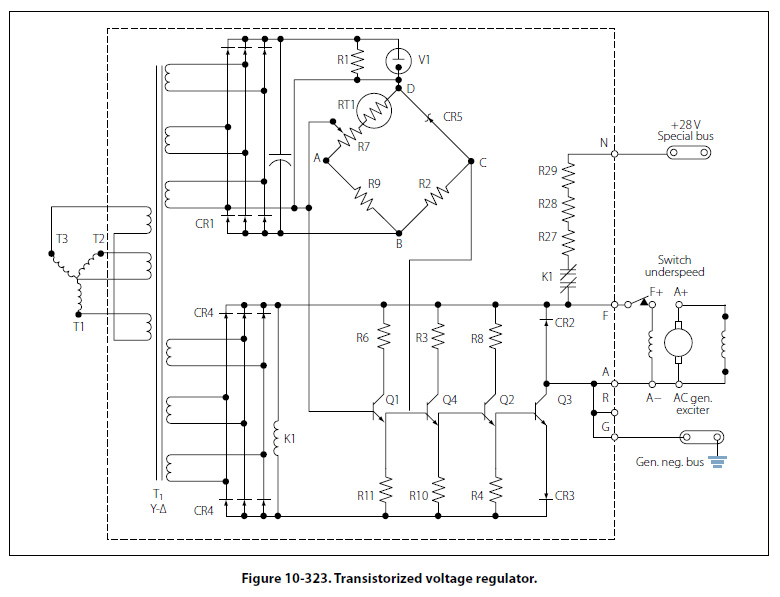
Voltage Regulation of Alternators The problem of voltage regulation in an AC system does not differ basically from that in a DC system. In each case, the function of the regulator system is to control voltage, maintain a balance of circulating current throughout the system, and eliminate sudden changes in voltage (anti-hunting) when a load is applied to the system. However, there is one important difference between the regulator system of DC generators and alternators operated in a parallel configuration. The load carried by any particular DC generator in either a two or four generator system depends on its voltage as compared with the bus voltage, while the division of load between alternators depends upon the adjustments of their speed governors, which are controlled by the frequency and droop circuits discussed in the previous section on alternator constant-speed drive systems. When AC generators are operated in parallel, frequency and voltage must both be equal. Where a synchronizing force is required to equalize only the voltage between DC generators, synchronizing forces are required to equalize both voltage and speed (frequency) between AC generators. On a comparative basis, the synchronizing forces for AC generators are much greater than for DC generators. When AC generators are of sufficient size and are operating at unequal frequencies and terminal voltages, serious damage may result if they are suddenly connected to each other through a common bus. To avoid this, the generators must be synchronized as closely as possible before connecting them together. Regulating the voltage output of a DC exciter, which supplies current to the alternator rotor field, best controls the output voltage of an alternator. This is accomplished by the regulation of a 28-volt system connected in the field circuit of the exciter. A regulator controls the exciter field current and thus regulates the exciter output voltage applied to the alternator field. Alternator Transistorized Regulators Many aircraft alternator systems use a transistorized voltage regulator to control the alternator output. Before studying this section, a review of transistor principles may be helpful. A transistorized voltage regulator consists mainly of transistors, diodes, resistors, capacitors, and, usually, a thermistor. In operation, current flows through a diode and transistor path to the generator field. When the proper voltage level is reached, the regulating components cause the transistor to cut off conduction to control the alternator field strength. The regulator operating range is usually adjustable through a narrow range. The thermistor provides temperature compensation for the circuitry. The transistorized voltage regulator shown in Figure 10-323 will be referred to in explaining the operation of this type of regulator.
The AC output of the generator is fed to the voltage regulator, where it is compared to a reference voltage, and the difference is applied to the control amplifier section of the regulator. If the output is too low, field strength of the AC exciter generator is increased by the circuitry in the regulator. If the output is too high, the field strength is reduced. The power supply for the bridge circuit is CR1, which provides full-wave rectification of the three phase output from transformer T1. The DC output voltages of CR1 are proportional to the average phase voltages. Power is supplied from the negative end of the power supply through point B, R2, point C, zener diode (CR5), point D, and to the parallel hookup of V1 and R1. Takeoff point C of the bridge is located between resistor R2 and the zener diode. In the other leg of the reference bridge, resistors R9, R7, and the temperature compensating resistor RT1 are connected in series with V1 and R1 through points B, A, and D. The output of this leg of the bridge is at the wiper arm of R7. As generator voltage changes occur, for example, if the voltage lowers, the voltage across R1 and V1 (once V2 starts conducting) will remain constant. The total voltage change will occur across the bridge circuit. Since the voltage across the zener diode remains constant (once it starts conducting), the total voltage change occurring in that leg of the bridge will be across resistor R2. In the other leg of the bridge, the voltage change across the resistors will be proportional to their resistance values. Therefore, the voltage change across R2 will be greater than the voltage change across R9 to wiper arm of R7. If the generator output voltage drops, point C will be negative with respect to the wiper arm of R7. Conversely, if the generator voltage output increases, the polarity of the voltage between the two points will be reversed. The bridge output, taken between points C and A, is connected between the emitter and the base of transistor Q1. With the generator output voltage low, the voltage from the bridge will be negative to the emitter and positive to the base. This is a forward bias signal to the transistor, and the emitter to collector current will therefore increase. With the increase of current, the voltage across emitter resistor R11 will increase. This, in turn, will apply a positive signal to the base of transistor Q4, increasing its emitter to collector current and increasing the voltage drop across the emitter resistor R10. This will give a positive bias to the base of Q2, which will increase its emitter to collector current and increase the voltage drop across its emitter resistor R4. This positive signal will control output transistor Q3. The positive signal on the base of Q3 will increase the emitter to collector current. The control field of the exciter generator is in the collector circuit. Increasing the output of the exciter generator will increase the field strength of the AC generator, which will increase the generator output. To prevent exciting the generator when the frequency is at a low value, there is an underspeed switch located near the F+ terminal. When the generator reaches a suitable operating frequency, the switch will close and allow the generator to be excited. Another item of interest is the line containing resistors R27, R28, and R29 in series with the normally closed contacts of the K1 relay. The operating coil of this relay is found in the lower left-hand part of the schematic. Relay K1 is connected across the power supply (CR4) for the transistor amplifier. When the generator is started, electrical energy is supplied from the 28-volt DC bus to the exciter generator field, to “flash the field" for initial excitation. When the field of the exciter generator has been energized, the AC generator starts to produce, and as it builds up, relay K1 is energized, opening the “field flash" circuit. |
| ©AvStop Online Magazine Contact Us Return To Books |