![]()
|
|
||
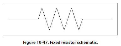
Types of Resistors Fixed Resistor Figure 10-47 is a schematic representation of a fixed resistor. Fixed resistors have built into the design a means of opposing current. The general use of a resistor in a circuit is to limit the amount of current flow. There are a number of methods used in construction and sizing of a resistor that control properties such as resistance value, the precision of the resistance value, and the ability to dissipate heat. While in some applications the purpose of the resistive element is used to generate heat, such as in propeller anti-ice boots, heat typically is the unwanted loss of energy.
Carbon Composition The carbon composed resistor is constructed from a mixture of finely grouped carbon/graphite, an insulation material for filler, and a substance for binding the material together. The amount of graphite in relation to the insulation material will determine the ohmic or resistive value of the resistor. This mixture is compressed into a rod, which is then fitted with axial leads or “pigtails." The finished product is then sealed in an insulating coating for isolation and physical protection. There are other types of fixed resistors in common use. Included in this group are:
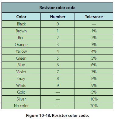
The construction of a film resistor is accomplished by depositing a resistive material evenly on a ceramic rod. This resistive material can be graphite for the carbon film resistor, nickel chromium for the metal film resistor, metal and glass for the metal glaze resistor and last, metal and an insulating oxide for the metal oxide resistor. Resistor Ratings It is very difficult to manufacture a resistor to an exact standard of ohmic values. Fortunately, most circuit requirements are not extremely critical. For many uses, the actual resistance in ohms can be 20 percent higher or lower than the value marked on the resistor without causing difficulty. The percentage variation between the marked value and the actual value of a resistor is known as the “tolerance" of a resistor. A resistor coded for a 5 percent tolerance will not be more than 5 percent higher or lower than the value indicated by the color code. The resistor color code is made up of a group of colors, numbers, and tolerance values. Each color is represented by a number, and in most cases, by a tolerance value. [Figure 10-48]
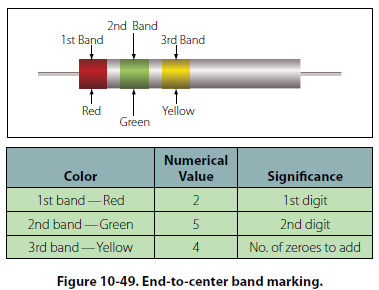
When the color code is used with the end-to-center band marking system, the resistor is normally marked with bands of color at one end of the resistor. The body or base color of the resistor has nothing to do with the color code, and in no way indicates a resistance value. To prevent confusion, this body will never be the same color as any of the bands indicating resistance value. When the end-to-center band marking system is used, either three or four bands will mark the resistor.
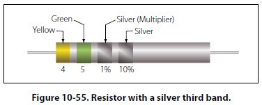
(b) If the third band is silver in color, the first two digits must be multiplied by 1 percent.
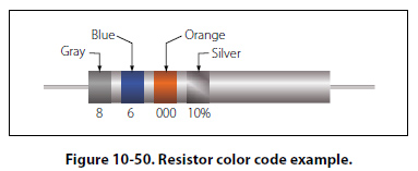
Figure 10-49 provides an example, which illustrates the rules for reading the resistance value of a resistor marked with the end-to-center band system. This resistor is marked with three bands of color, which must be read from the end toward the center. There is no fourth color band; therefore, the tolerance is understood to be 20 percent. 20 percent of 250,000 O, equals 50,000 O. Since the 20 percent tolerance is plus or minus, Maximum resistance = 250,000 O + 50,000 O Minimum resistance = 250,000 O - 50,000 O The following paragraphs provide a few extra examples of resistor color band decoding. Figure 10-50 contains a resistor with another set of colors. This resistor code should be read as follows:
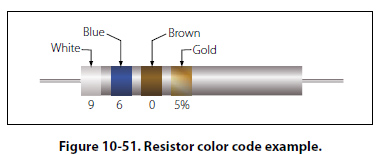
The resistance of this resistor is 86,000 ± 10 percent ohms. The maximum resistance is 94,600 ohms, and the minimum resistance is 77,400 ohms. As another example, the resistance of the resistor in Figure 10-51 is 960 ± 5 percent ohms. The maximum resistance is 1,008 ohms, and the minimum resistance is 912 ohms.
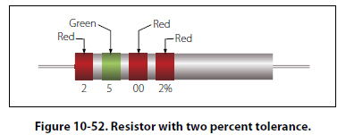
Sometimes circuit considerations dictate that the tolerance must be smaller than 20 percent. Figure 10-52 shows an example of a resistor with a 2 percent tolerance. The resistance value of this resistor is 2,500 ± 2 percent ohms. The maximum resistance is 2,550 ohms, and the minimum resistance is 2,450 ohms.
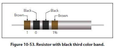
Figure 10-53 contains an example of a resistor with a black third color band. The color code value of black is zero, and the third band indicates the number of zeros to be added to the first two digits.
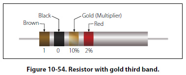
In this case, a zero number of zeros must be added to the first two digits; therefore, no zeros are added. Thus, the resistance value is 10 ± 1 percent ohms. The maximum resistance is 10.1 ohms, and the minimum resistance is 9.9 ohms. There are two exceptions to the rule stating the third color band indicates the number of zeros. The first of these exceptions is illustrated in Figure 10-54. When the third band is gold in color, it indicates that the first two digits must be multiplied by 10 percent. The value of this resistor in this case is: 10 × 0.10 ± 2% = 1 = 0.02 ohms
When the third band is silver, as is the case in Figure 10- 55, the first two digits must be multiplied by 1 percent. The value of the resistor is 0.45 ± 10 percent ohms.
|
| ©AvStop Online Magazine Contact Us Return To Books |