![]()
|
|
||
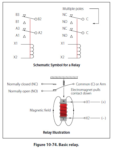
DIP Switches The acronym “DIP" switch is defined as Dual In-Line Parallel switch in reference to the physical layout. DIP switches are commonly found in card cages, and line replaceable units (LRU) are used in most cases to adjust gains, control configurations, and so forth. Each one of the switches is generally an SPST slide or rocker switch. The technician may find this switch in packages ranging in size from DIP2 through DIP32. Some of the more common sizes are DIP4 and DIP8. Switch Guards Switch guards are covers that protect a switch from unintended operation. Prior to the operation of the switch, the guard is usually lifted. Switch guards are commonly found on systems such as fire suppression and override logics for various systems. Relays A relay is simply an electromechanical switch where a small amount of current can control a large amount of current. Figure 10-74 illustrates the basic relay in
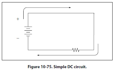
both schematic and pictorial format. When a voltage is applied to the coil of the relay, the electromagnet will be energized due to the current. When energized, an electromagnetic field will pull the common (C) or arm of the relay down. When the arm or common is pulled down, the circuit between the arm and the normally closed (NC) contacts is opened and the circuit between the arm and the normally open (NO) contacts are closed. When the energizing voltage is removed, the spring will return the arm contacts back to the normally closed (NC) contacts. The relay usually has two connections for the coil. The (+) side is designated as X1 and the ground-side of the coil is designated as X2. Series DC Circuits Introduction The series circuit is the most basic electrical circuit and provides a good introduction to basic circuit analysis. The series circuit represents the first building block for all of the circuits to be studied and analyzed. Figure 10- 75 shows this simple circuit with nothing more than a voltage source or battery, a conductor, and a resistor. This is classified as a series circuit because the components are connected end-to-end, so that the same current flows through each component equally. There is only one path for the current to take and the battery and resistor are in series with each other. Next is to make a few additions to the simple circuit in Figure 10-75.
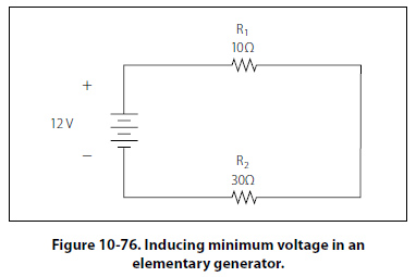
Figure 10-76 shows an additional resistor and a little more detail regarding the values. With these values, we can now begin to learn more about the nature of the circuit. In this configuration, there is a 12-volt DC source in series with two resistors, R1 = 10 O and R2 = 30 O. For resistors in a series configuration, the total resistance of the circuit is equal to the sum of the individual resistors. The basic formula is:
RT = R1 + R2 + R3 + ………RN For Figure 10-76, this will be: RT = 10O + 30O Now that the total resistance of the circuit is known, the current for the circuit can be determined. In a series circuit, the current cannot be different at different points within the circuit. The current through a series circuit will always be the same through each element and at any point. Therefore, the current in the simple circuit can now be determined using Ohm’s law: Formula, E = I (R) Ohm’s law describes a relationship between the variables of voltage, current, and resistance that is linear and easy to illustrate with a few extra calculations. First will be the act of changing the total resistance of the circuit while the other two remain constant. In this example, the RT of the circuit in Figure 10-76 will be doubled. The effects on the total current in the circuit are: Formula, E = I (R) It can be seen quantitatively and intuitively that when the resistance of the circuit is doubled, the current is reduced by half the original value. Next, reduce the RT of the circuit in Figure 10-76 to half of its original value. The effects on the total current are: Formula, E = I (R) |
| ©AvStop Online Magazine Contact Us Return To Books |