![]()
|
|
||
Current Dividers It can now be easily seen that the parallel circuit is a current divider. As could be seen in Figure 10-90, there is a current through each of the two resistors. Because the same voltage is applied across both resistors in parallel, the branch currents are inversely proportional to the ohmic values of the resistors. Branches with higher resistance have less current than those with lower resistance. For example, if the resistive value of R2 is twice as high as that of R1, the current in R2 will be half of that of R1. All of this can be determined with Ohm’s law. By Ohm’s law, the current through any one of the branches can be written as: IX = ES/RX The voltage source appears across each of the parallel resistors and RX represents any one the resistors. The source voltage is equal to the total current times the total parallel resistance.
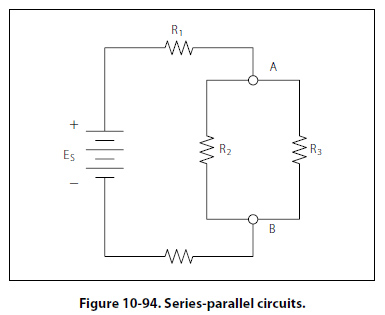
This formula is the general current divider formula. The current through any branch equals the total parallel resistance divided by the individual branch resistance, multiplied by the total current. Series-Parallel DC Circuits Overview Most of the circuits that the technician will encounter will not be a simple series or parallel circuit. Circuits are usually a combination of both, known as series-parallel circuits, which are groups consisting of resistors in parallel and in series. An example of this type of circuit can be seen in Figure 10-94. While the series-parallel circuit can initially appear to be complex, the same rules that have been used for the series and parallel circuits can be applied to these circuits.
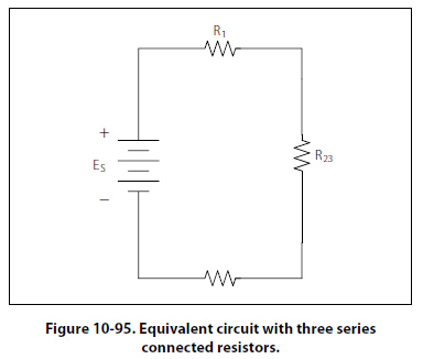
The voltage source will provide a current out to resistor R1, then to the group of resistors R2 and R3 and then to the next resistor R4 before returning to the voltage source. The first step in the simplification process is to isolate the group R2 and R3 and recognize that they are a parallel network that can be reduced to an equivalent resistor. Using the formula for parallel resistance, R23 = R2R3/R2 + R3 R2 and R3 can be reduced to R23. Figure 10-95 now shows an equivalent circuit with three series connected resistors. The total resistance of the circuit can now be simply determined by adding up the values of resistors R1, R23, and R4.
|
| ©AvStop Online Magazine Contact Us Return To Books |

.jpg)