![]()
|
|
||
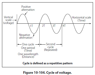
Position 3 At this point, the conductor has made one-half of a revolution and again moves parallel to the lines of force, and no voltage is induced in the conductor. As the A conductor passes position 3, the direction of induced voltage now reverses since the A conductor is moving downward, cutting flux in the opposite direction. As the A conductor moves across the south pole, the induced voltage gradually increases in a negative direction, until it reaches position 4. Position 4 Like position 2, the conductor is again moving perpendicular to the flux and generates a maximum negative voltage. From position 4 to 5, the induced voltage gradually decreases until the voltage is zero, and the conductor and wave are ready to start another cycle. Position 5 The curve shown at position 5 is called a sine wave. It represents the polarity and the magnitude of the instantaneous values of the voltages generated. The horizontal base line is divided into degrees, or time, and the vertical distance above or below the base line represents the value of voltage at each particular point in the rotation of the loop. Cycle and Frequency Cycle Defined A cycle is a repetition of a pattern. Whenever a voltage
or current passes through a series of changes, returns
to the starting point, and then again starts the same
series of changes, the series is called a cycle. The
cycle is represented by the symbol of a wavy line in
a circle
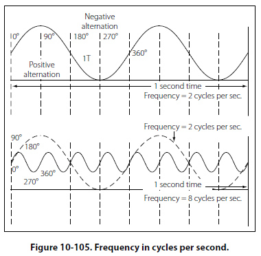
Frequency Defined The frequency is the number of cycles of alternating current per second (1 second). The standard unit of frequency measurement is the hertz (Hz). [Figure 10-105]
In a generator, the voltage and current pass through a complete cycle of values each time a coil or conductor passes under a north and south pole of the magnet. The number of cycles for each revolution of the coil or conductor is equal to the number of pairs of poles. The frequency, then, is equal to the number of cycles in one revolution multiplied by the number of revolutions per second. Expressed in equation form, F = Number of poles/2 × rpm/60 where P/2 is the number of pairs of poles, and rpm/60 the number of revolutions per second. If in a 2 pole generator, the conductor is turning at 3,600 rpm, the revolutions per second are rps = 3600/60 = 60 revolutions per second Since there are 2 poles, P/2 is 1, and the frequency is 60 cycles per second (cps). In a 4 pole generator with an armature speed of 1,800 rpm, substitute in the equation, F =P/2 × rpm/60 as follows |
| ©AvStop Online Magazine Contact Us Return To Books |