![]()
|
|
||
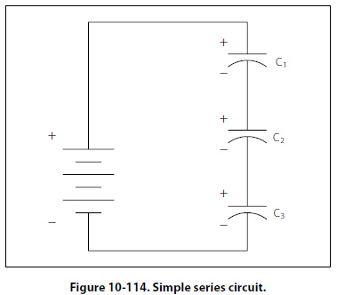
Variable Capacitors Variable capacitors are mostly used in radio tuning circuits, and they are sometimes called “tuning capacitors." They have very small capacitance values, typically between 100pF and 500pF. Trimmers The trimmer is actually an adjustable or variable capacitor, which uses ceramic or plastic as a dielectric. Most of them are color coded to easily recognize their tunable size. The ceramic type has the value printed on them. Colors are: yellow (5pF), blue (7pF), white (10pF), green (30pF), and brown (60pf). Varactors A voltage-variable capacitor or varactor is also known as a variable capacitance diode or a varicap. This device utilizes the variation of the barrier width in a reversed-biased diode. Because the barrier width of a diode acts as a non-conductor, a diode forms a capacitor when reversed biased. Essentially the N-type material becomes one plate and the junctions are the dielectric. If the reversed-bias voltage is increased, then the barrier width widens, effectively separating the two capacitor plates and reducing the capacitance. Capacitors in Series When capacitors are placed in series, the effective plate separation is increased and the total capacitance is less than that of the smallest capacitor. Additionally, the series combination is capable of withstanding a higher total potential difference than any of the individual capacitors. Figure 10-114 is a simple series circuit.
QT = Q1 + Q2 + Q3 According to Kirchhoff’s voltage law, the sum of the voltages across the charged capacitors must equal the total voltage, ET. This is expressed as: ET = E1 + E2 + E3 Equation E = Q/C can now be substituted into the voltage equation where we now get: QT/CT= Q1/C1+Q2/C2+Q3/C3 Since the charge on all capacitors is equal, the Q terms can be factored out, leaving us with the equation: 1/CT= 1/C1+1/C2+1/C3 Consider the following example: If C1 = 10µF, C2 = 5µF and C3 = 8µF |
| ©AvStop Online Magazine Contact Us Return To Books |