![]()
|
|
||
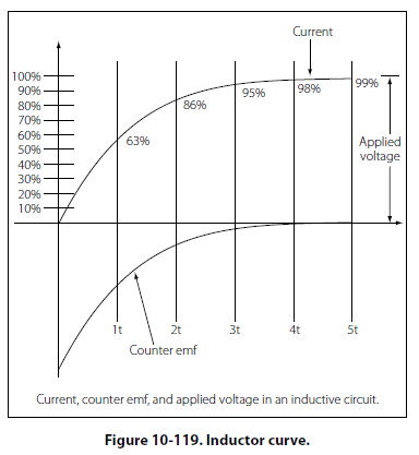
The RL Time Constant Because the inductors basic action is to oppose a change in its current, it then follows that the current cannot change instantaneously in the inductor. A certain time is required for the current to make a change from one value to another. The rate at which the current changes is determined by a time constant represented by the greek letter tau (τ). The time constant for the RL circuit is: τ =L/R In a series RL circuit, the current will increase to 63% of its full value in 1 time constant after the circuit is closed. This build up of course is similar to the build up of voltage in a capacitor when charging an RC circuit. Both follow an exponential curve and reach 99% value after the 5th time constant. Figure 10-119 illustrates this characteristic.
Physical Parameters Some of the physical factors that affect inductance are:
Self-Inductance The characteristic of self-inductance was summarized by German physicist Heinrich Lenz in 1833 and gives the direction of the induced electromotive force (emf) resulting from electromagnetic induction. This is commonly known as Lenz’s Law, which states: The emf induced in an electric circuit always acts in such a direction that the current it drives around a closed circuit produces a magnetic field which opposes the change in magnetic flux. Self inductance is the generation of a voltage in an electric circuit by a changing current in the same circuit. Even a straight piece of wire will have some degree of inductance because current in a conductor produces a magnetic field. When the current in a conductor changes direction, there will be a corresponding change in the polarity of the magnetic field around the conductor. Therefore, a changing current produces a changing magnetic field around the wire. To further intensify the magnetic field, the wire can be rolled into a coil, which is called an inductor. The changing magnetic field around the inductor induces a voltage across the coil. This induced electromotive force is called self-inductance and tends to oppose any change in current within the circuit. This property is usually called inductance and symbolized with the letter L. |
| ©AvStop Online Magazine Contact Us Return To Books |