
![]()
|
|
||
Types of Inductors Inductors used in radio can range from a straight wire at UHF to large chokes and transformers used for filtering the ripple from the output of power supplies and in audio amplifiers. Figure 10-69 shows the schematic symbols for common inductors. Values of inductors range from nano-henries to tens of henries. Inductors are classified by the type of core and the method of winding them. The number of turns in the inductor winding and the core material determine the capacity of the inductor. Cores made of dielectric material like ceramics, wood, paper provide small amounts of stored energy while cores made of ferrite substances have a much higher degree of stored energy. The core material is usually the most important aspect of the inductors construction. The conductors typically used in the construction of an inductor offer little resistance to the flow of current. However, with the introduction of a core, resistance is introduced in the circuit and the current now builds up in the windings until the resistance of the core is overcome. This buildup is stored as magnetic energy in the core. Depending on the core resistance, the buildup soon reaches a point of magnetic saturation and it can be released when necessary. The most common core materials are: Air, solid ferrite, powdered ferrite, steel, toroid and ferrite toroid. Units of Inductance The henry is the basic unit of inductance and is symbolized with the letter H. An electric circuit has an inductance of one henry when current changing at the rate of one ampere per second induces a voltage of one volt into the circuit. In many practical applications, millihenries (mH) and microhenries (µH) are more common units. The typical symbol for an inductor is shown in Figure 10-120.
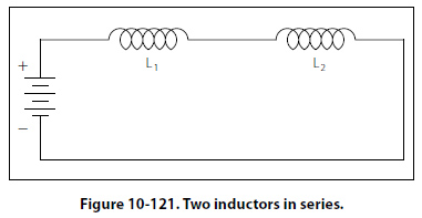
Inductors in Series If we connect two inductors in series as shown in Figure 10-121, the same current flows through both inductors and, therefore, both will be subject to the same rate of change of current. When inductors are connected in series, the total inductance LT, is the sum of the individual inductors. The general equation for n number of inductors in series is:
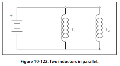
LT = L1 + L2 + L3 + … LN Inductors in Parallel When two inductors are connected in parallel as shown in Figure 10-122, each must have the same potential difference between the terminals. When inductors are connected in parallel, the total inductance is less than
the smallest inductance. The general equation for n number of inductors in parallel is:
|
| ©AvStop Online Magazine Contact Us Return To Books |

.jpg)