
![]()
|
|
||
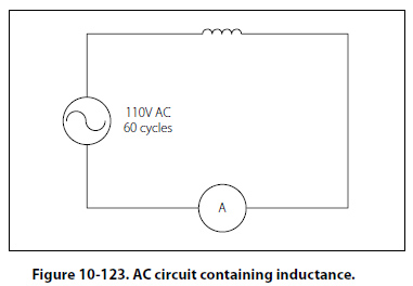
Inductive Reactance Alternating current is in a constant state of change; the effects of the magnetic fields are a continuously inducted voltage opposition to the current in the circuit. This opposition is called inductive reactance, symbolized by XL, and is measured in ohms just as resistance is measured. Inductance is the property of a circuit to oppose any change in current and is measured in henries. Inductive reactance is a measure of how much the countering emf in the circuit will oppose current variations. The inductive reactance of a component is directly proportional to the inductance of the component and the applied frequency to the circuit. By increasing either the inductance or applied frequency, the inductive reactance will likewise increase and present more opposition to current in the circuit. This relationship is given as:
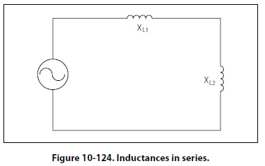
In any circuit where there is only resistance, the expression for the relationship of voltage and current is given by Ohm’s law: I = E/ R. Similarly, when there is inductance in an AC circuit, the relationship between voltage and current can be expressed as: Current = Voltage / Reactance Or I =E/XL In AC series circuits, inductive reactances are added like resistances in series in a DC circuit. [Figure 10- 124] Thus, the total reactance in the illustrated circuit equals the sum of the individual reactances.
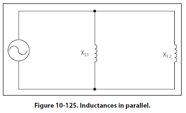
The total reactance of inductors connected in parallel is found the same way as the total resistance in a parallel circuit. [Figure 10-125] Thus, the total reactance of inductances connected in parallel, as shown, is expressed as
|
| ©AvStop Online Magazine Contact Us Return To Books |

.jpg)
).jpg)