
![]()
|
|
||
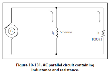
Parallel AC Circuits The methods used in solving parallel AC circuit problems are basically the same as those used for series AC circuits. Out of phase voltages and currents can be added by using the law of right triangles. However, in solving circuit problems, the currents through the branches are added since the voltage drops across the various branches are the same and are equal to the applied voltage.
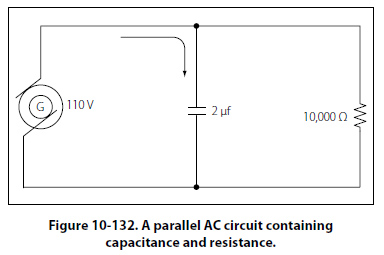
Since inductive reactance causes voltage to lead the current, the total current, which contains a component of inductive current, lags the applied voltage. If the current and voltages are plotted, the angle between the two, called the phase angle, illustrates the amount the current lags the voltage. In Figure 10-132, a 110-volt generator is connected to a load consisting of a 2 µf capacitance and a 10,000- ohm resistance in parallel. What is the value of the impedance and total current flow?
|
| ©AvStop Online Magazine Contact Us Return To Books |

.jpg)
).jpg)