![]()
|
|
||
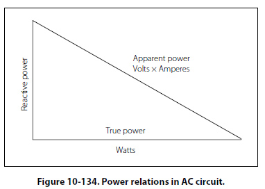
Power in AC Circuits In a DC circuit, power is obtained by the equation, P = EI, (watts equal volts times amperes). Thus, if 1 ampere of current flows in a circuit at a pressure of 200 volts, the power is 200 watts. The product of the volts and the amperes is the true power in the circuit. True Power Defined The power dissipated in the resistance of a circuit, or the power actually used in the circuit. In an AC circuit, a voltmeter indicates the effective voltage and an ammeter indicates the effective current. The product of these two readings is called the apparent power. Apparent Power Defined That power apparently available for use in an AC circuit containing a reactive component. It is the product of effective voltage times the effective current, expressed in volt-amperes. It must be multiplied by the power factor to obtain true power available. Only when the AC circuit is made up of pure resistance is the apparent power equal to the true power. [Figure 10-134] When there is capacitance or inductance in the circuit, the current and voltage are not exactly in phase, and the true power is less than the apparent power. The true power is obtained by a wattmeter reading. The ratio of the true power to the apparent power is called the power factor and is usually expressed in percent. In equation form, the relationship is:
Power Factor (PF) =100 × Watts (True Power)/Volts × Amperes (Apparent Power) Example: A 220-volt AC motor takes 50 amperes from the line, but a wattmeter in the line shows that only 9,350 watts are taken by the motor. What are the apparent power and the power factor?
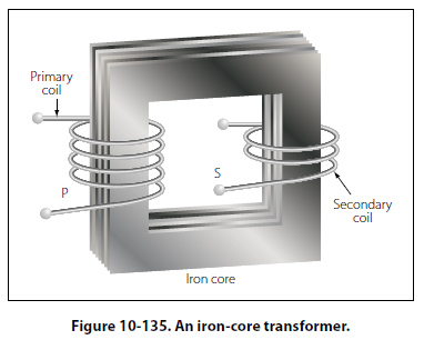
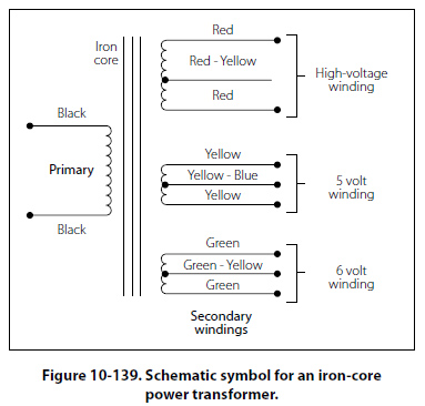
Transformers A transformer changes electrical energy of a given voltage into electrical energy at a different voltage level. It consists of two coils that are not electrically connected, but are arranged so that the magnetic field surrounding one coil cuts through the other coil. When an alternating voltage is applied to (across) one coil, the varying magnetic field set up around that coil creates an alternating voltage in the other coil by mutual induction. A transformer can also be used with pulsating DC, but a pure DC voltage cannot be used, since only a varying voltage creates the varying magnetic field that is the basis of the mutual induction process. A transformer consists of three basic parts. [Figure 10- 135] These are an iron core which provides a circuit of low reluctance for magnetic lines of force, a primary winding which receives the electrical energy from the source of applied voltage, and a secondary winding which receives electrical energy by induction from the primary coil.
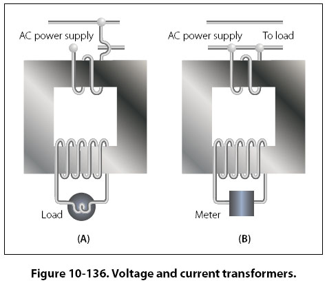
The primary and secondary of this closed core transformer are wound on a closed core to obtain maximum inductive effect between the two coils. There are two classes of transformers: (1) voltage transformers used for stepping up or stepping down voltages, and (2) current transformers used in instrument circuits. In voltage transformers, the primary coils are connected in parallel across the supply voltage as shown in Figure 10-136A. The primary windings of current transformers are connected in series in the primary circuit [Figure 10-136B]. Of the two types, the voltage transformer is the more common.
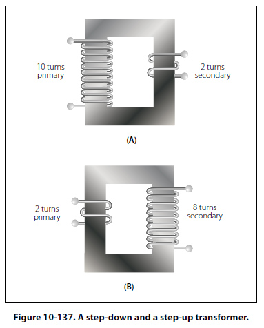
There are many types of voltage transformers. Most of these are either step-up or step-down transformers. The factor that determines whether a transformer is a step-up, or step-down type is the “turns" ratio. The turns ratio is the ratio of the number of turns in the primary winding to the number of turns in the secondary winding. For example, the turns ratio of the step-down transformer shown in Figure 10-137A is 5 to 1, since there are five times as many turns in the primary as in the secondary. The step-up transformer shown in Figure 10-137B has a 1 to 4 turns ratio.
The ratio of the transformer input voltage to the output voltage is the same as the turns ratio if the transformer is 100 percent efficient. Thus, when 10 volts are applied to the primary of the transformer shown in Figure 10- 137A, two volts are induced in the secondary. If 10 volts are applied to the primary of the transformer in Figure 10-137B, the output voltage across the terminals of the secondary will be 40 volts. No transformer can be constructed that is 100 percent efficient, although iron core transformers can approach this figure. This is because all the magnetic lines of force set up in the primary do not cut across the turns of the secondary coil. A certain amount of the magnetic flux, called leakage flux, leaks out of the magnetic circuit. The measure of how well the flux of the primary is coupled into the secondary is called the “coefficient of coupling." For example, if it is assumed that the primary of a transformer develops 10,000 lines of force and only 9,000 cut across the secondary, the coefficient of coupling would be 0.9 or, stated another way, the transformer would be 90 percent efficient. When an AC voltage is connected across the primary terminals of a transformer, an alternating current will flow and self induce a voltage in the primary coil that is opposite and nearly equal to the applied voltage. The difference between these two voltages allows just enough current in the primary to magnetize its core. This is called the exciting, or magnetizing, current. The magnetic field caused by this exciting current cuts across the secondary coil and induces a voltage by mutual induction. If a load is connected across the secondary coil, the load current flowing through the secondary coil will produce a magnetic field which will tend to neutralize the magnetic field produced by the primary current. This will reduce the self-induced (opposition) voltage in the primary coil and allow more primary current to flow. The primary current increases as the secondary load current increases, and decreases as the secondary load current decreases. When the secondary load is removed, the primary current is again reduced to the small exciting current sufficient only to magnetize the iron core of the transformer. If a transformer steps up the voltage, it will step down the current by the same ratio. This should be evident if the power formula is considered, for the power (I × E) of the output (secondary) electrical energy is the same as the input (primary) power minus that energy loss in the transforming process. Thus, if 10 volts and 4 amps (40 watts of power) are used in the primary to produce a magnetic field, there will be 40 watts of power developed in the secondary (disregarding any loss). If the transformer has a step-up ratio of 4 to 1, the voltage across the secondary will be 40 volts and the current will be 1 amp. The voltage is 4 times greater and the current is one-fourth the primary circuit value, but the power (I × E value) is the same. When the turns ratio and the input voltage are known, the output voltage can be determined as follows: E2/E1 = N2/N1 Where E is the voltage of the primary, E2 is the output voltage of the secondary, and N1 and N2 are the number of turns of the primary and secondary, respectively. Transposing the equation to find the output voltage gives: E2 = E1N2/N1
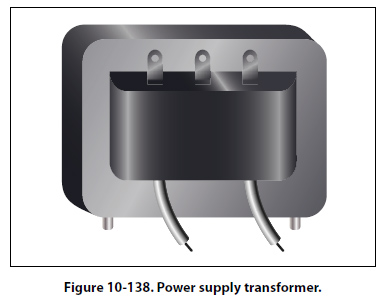
The most commonly used types of voltage transformers are as follows:
|
| ©AvStop Online Magazine Contact Us Return To Books |

.jpg)