![]()
|
|
||
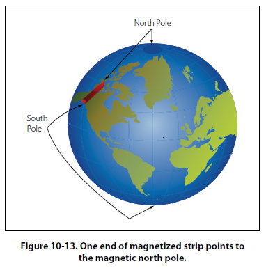
Magnetism Magnetism is defined as the property of an object to attract certain metallic substances. In general, these substances are ferrous materials; that is, materials composed of iron or iron alloys, such as soft iron, steel, and alnico. These materials, sometimes called magnetic materials, today include at least three nonferrous materials: nickel, cobalt, and gadolinium, which are magnetic to a limited degree. All other substances are considered nonmagnetic, and a few of these nonmagnetic substances can be classified as diamagnetic since they are repelled by both poles of a magnet. Magnetism is an invisible force, the ultimate nature of which has not been fully determined. It can best be described by the effects it produces. Examination of a simple bar magnet similar to that illustrated in Figure 10-13 discloses some basic characteristics of all magnets.
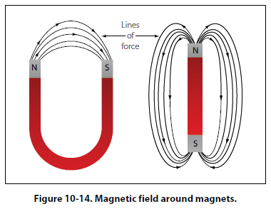
The somewhat mysterious and completely invisible force of a magnet depends on a magnetic field that surrounds the magnet as illustrated in Figure 10-14. This field always exists between the poles of a magnet, and will arrange itself to conform to the shape of any magnet.
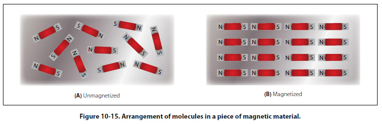
The theory that explains the action of a magnet holds that each molecule making up the iron bar is itself a tiny magnet, with both north and south poles as illustrated in Figure 10-15A. These molecular magnets each possess a magnetic field, but in an unmagnetized state,
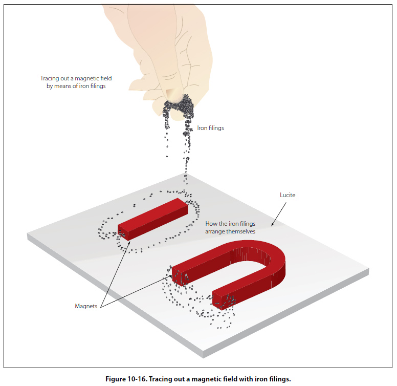
the molecules are arranged at random throughout the iron bar. If a magnetizing force, such as stroking with a lodestone, is applied to the unmagnetized bar, the molecular magnets rearrange themselves in line with the magnetic field of the lodestone, with all north ends of the magnets pointing in one direction and all south ends in the opposite direction. This is illustrated in Figure 10-15B. In such a configuration, the magnetic fields of the magnets combine to produce the total field of the magnetized bar. When handling a magnet, avoid applying direct heat, or hammering or dropping it. Heating or sudden shock will cause misalignment of the molecules, causing the strength of a magnet to decrease. When a magnet is to be stored, devices known as “keeper bars" are installed to provide an easy path for flux lines from one pole to the other. This promotes the retention of the molecules in their north-south alignment. The presence of the magnetic force or field around a magnet can best be demonstrated by the experiment illustrated in Figure 10-16. A sheet of transparent material, such as glass or Lucite™, is placed over a
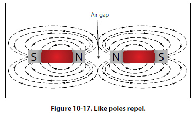
bar magnet and iron filings are sprinkled slowly on this transparent shield. If the glass or Lucite is tapped lightly, the iron filings will arrange themselves in a definite pattern around the bar, forming a series of lines from the north to south end of the bar to indicate the pattern of the magnetic field. As shown, the field of a magnet is made up of many individual forces that appear as lines in the iron filing demonstration. Although they are not “lines" in the ordinary sense, this word is used to describe the individual nature of the separate forces making up the entire magnetic field. These lines of force are also referred to as magnetic flux. They are separate and individual forces, since one line will never cross another; indeed, they actually repel one another. They remain parallel to one another and resemble stretched rubber bands, since they are held in place around the bar by the internal magnetizing force of the magnet. The demonstration with iron filings further shows that the magnetic field of a magnet is concentrated at the ends of the magnet. These areas of concentrated flux are called the north and south poles of the magnet. There is a limit to the number of lines of force that can be crowded into a magnet of a given size. When a magnetizing force is applied to a piece of magnetic material, a point is reached where no more lines of force can be induced or introduced. The material is then said to be saturated. The characteristics of the magnetic flux can be demonstrated by tracing the flux patterns of two bar magnets with like poles together, as shown in Figure 10-17. The two like poles repel one another because the lines of force will not cross each other. As the arrows on the individual lines indicate, the lines turn aside as the two like poles are brought near each other and travel in a
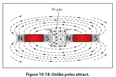
path parallel to each other. Lines moving in this manner repel each other, causing the magnets as a whole to repel each other. By reversing the position of one of the magnets, the attraction of unlike poles can be demonstrated, as shown in Figure 10-18.
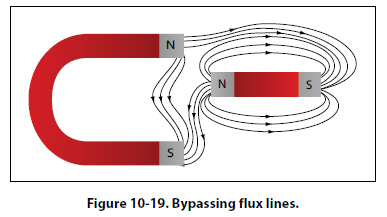
As the unlike poles are brought near each other, the lines of force rearrange their paths and most of the flux leaving the north pole of one magnet enters the south pole of the other. The tendency of lines of force to repel each other is indicated by the bulging of the flux in the air gap between the two magnets. To further demonstrate that lines of force will not cross one another, a bar magnet and a horseshoe magnet can be positioned to display a magnetic field similar to that of Figure 10-19. The magnetic fields of the two magnets do not combine, but are rearranged into a distorted flux pattern.
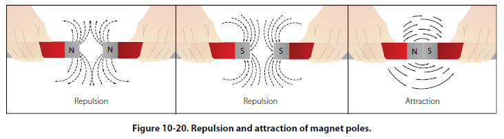
The two bar magnets may be held in the hands and the north poles brought near each other to demonstrate the force of repulsion between like poles. In a similar manner, the two south poles can demonstrate this force. The force of attraction between unlike poles can be felt by bringing a south and a north end together. These experiments are illustrated in Figure 10-20.
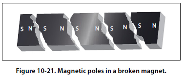
Figure 10-21 illustrates another characteristic of magnets. If the bar magnet is cut or broken into pieces,
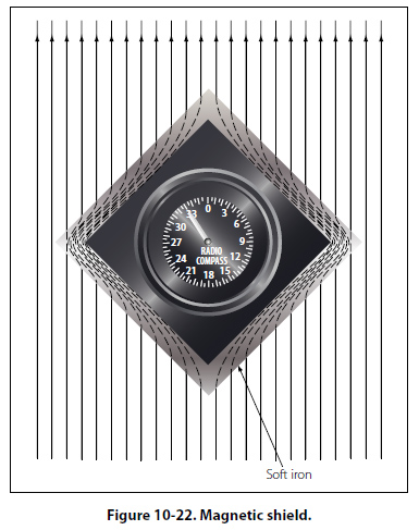
each piece immediately becomes a magnet itself, with a north and south pole. This feature supports the theory that each molecule is a magnet, since each successive division of the magnet produces still more magnets. Since the magnetic lines of force form a continuous loop, they form a magnetic circuit. It is impossible to say where in the magnet they originate or start. Arbitrarily, it is assumed that all lines of force leave the north pole of any magnet and enter at the south pole. There is no known insulator for magnetic flux, or lines of force, since they will pass through all materials. However, they will pass through some materials more easily than others. Thus it is possible to shield items such as instruments from the effects of the flux by surrounding them with a material that offers an easier path for the lines of force. Figure 10-22 shows an instrument surrounded by a path of soft iron, which offers very little opposition to magnetic flux. The lines of force take the easier path, the path of greater permeability, and are guided away from the instrument.
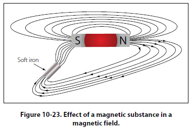
Materials such as soft iron and other ferrous metals are said to have a high permeability, the measure of the ease with which magnetic flux can penetrate a material. The permeability scale is based on a perfect vacuum with a rating of one. Air and other nonmagnetic materials are so close to this that they are also considered to have a rating of one. The nonferrous metals with a permeability greater than one, such as nickel and cobalt, are called paramagnetic. The term ferromagnetic is applied to iron and its alloys, which have by far the greatest permeability. Any substance, such as bismuth, having a permeability of less than one, is considered diamagnetic. Reluctance, the measure of opposition to the lines of force through a material, can be compared to the resistance of an electrical circuit. The reluctance of soft iron, for instance, is much lower than that of air. Figure 10-23 demonstrates that a piece of soft iron placed near the field of a magnet can distort the lines of force, which follow the path of lowest reluctance through the soft iron.
The magnetic circuit can be compared in many respects to an electrical circuit. The magnetomotive force, causing lines of force in the magnetic circuit, can be compared to the electromotive force or electrical pressure of an electrical circuit. The magnetomotive force is measured in gilberts, symbolized by the capital letter “F." The symbol for the intensity of the lines of force, or flux, is the Greek letter phi, and the unit of field intensity is the gauss. An individual line of force, called a maxwell, in an area of one square centimeter produces a field intensity of one gauss. Using reluctance rather than permeability, the law for magnetic circuits can be stated: a magnetomotive force of one gilbert will cause one maxwell, or line of force, to be set up in a material when the reluctance of the material is one. |
| ©AvStop Online Magazine Contact Us Return To Books |