![]()
|
|
||
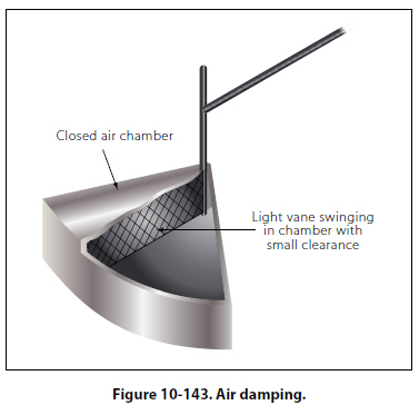
Damping To make meter readings quickly and accurately, it is desirable that the moving pointer overshoot its proper position only a small amount and come to rest after not more than one or two small oscillations. The term “damping" is applied to methods used to bring the pointer of an electrical meter to rest after it has been set in motion. Damping may be accomplished by electrical means, by mechanical means, or by a combination of both. Electrical Damping A common method of damping by electrical means is to wind the moving coil on an aluminum frame. As the coil moves in the field of the permanent magnet, eddy currents are set up in the aluminum frame. The magnetic field produced by the eddy currents opposes the motion of the coil. The pointer will therefore swing more slowly to its proper position and come to rest quickly with very little oscillation. Mechanical Damping Air damping is a common method of damping by mechanical means. As shown in Figure 10-143, a vane is attached to the shaft of the moving element and enclosed in an air chamber. The movement of the shaft is retarded because of the resistance that the air offers to the vane. Effective damping is achieved if the vane nearly touches the walls of the chamber.
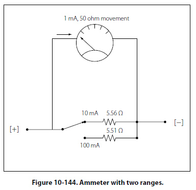
A Basic Multirange Ammeter Building upon the basic meter previously discussed is the more complex and useful multirange meter, which is more practical. The basic idea of a multirange ammeter is to make the meter usable over a wide range of voltages. In order to accomplish this, each range must utilize a different shunt resistance. The example give in this text is that of a two-range meter. However, once the basics of a two range multirange ammeter are understood, the concepts can easily be transferred to the design of meters with many selectable ranges. Figure 10-144 shows the schematic of an ammeter with two selectable ranges. This example builds upon the previous 10mA range meter by adding a 100mA range. With the switch selected to the 10mA range, the meter will indicate 10mA when the needle is deflected to full scale and will likewise indicate 100mA at full scale when selected to 100mA.
The value of the 100mA shunt resistor is determined the same way the 10mA shunt resistor was determined. Recall that the meter movement can only carry 1mA. This means that in a 100mA range the remaining current of 99mA must pass through the shunt resistor. RSH =IM × RM/ISH Substituting the values RSH =ImA × 50O/99mA = 0.51O |
| ©AvStop Online Magazine Contact Us Return To Books |