![]()
|
|
||
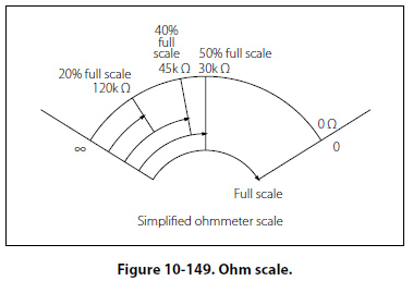
Ohmmeter Scale Figure 10-149 shows a typical analog ohmmeter scale. Between zero and infinity (8), the scale is marked to indicate various resistor values. Because the values decrease from left to right, this scale is often called a back-off scale.
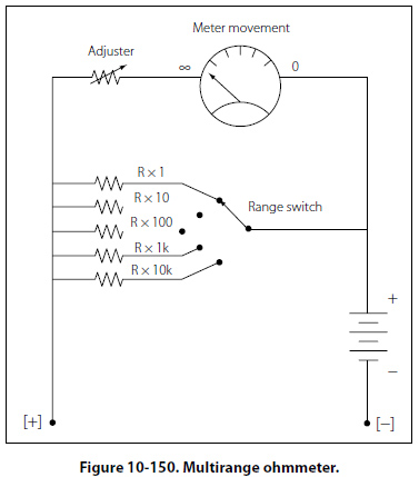
In the case of the example given, assume that a certain ohmmeter uses a 50µA, 1000O meter movement and has an internal 1.5 volt battery. A current of 50µA produces a full-scale deflection when the test leads are shorted. To have 50µA, the total ohmmeter resistance is 1.5 V/50µA = 30kO. Therefore, since the coil resistance is 1kO, the variable zero adjustment resistor must be set to 30kO – 1kO = 29kO. Now consider that a 120kO resistor is connected to the ohmmeter leads. Combined with the 30kO internal resistance, the total R is 150kO. The current is 1.5 V/150kO = 10µA, which is 20% of the full scale current and which appears on the scale as shown in Figure 10-149. Now consider further that a 120kO resistor is connected to the ohmmeter leads. This will result in a current of 1.5V/75kO = 10µA, which is 40% of the full scale current and which is marked on the scale as shown. Additional calculations of this type show that the scale is nonlinear. It is more compressed toward the left side than the right side. The center scale point corresponds to the internal meter resistance of 30kO. The reason is as follows: With 30kO connected to the leads, the current is 1.5V/60kO = 25µA, which is half of the full scale current of 50µA. The Multirange Ohmmeter A practical ohmmeter usually has several operational ranges. These typically are indicated by R × 1, R × 10, R × 100, R × 1k, R × 100k and R × 1M. These range selections are interpreted in a different manner than that of an ammeter or voltmeter. The reading on the ohmmeter scale is multiplied by the factor indicated by the range setting. For example, if the pointer is set on the scale and the range switch is set at R × 100, the actual resistance measurement is 20 × 100 or 2kO. To measure small resistance values, the technician must use a higher ohmmeter current than is needed for measuring large resistance values. Shunt resistors are needed to provide multiple ranges on the ohmmeter to measure a range of resistance values from the very small to very large. For each range, a different value of shunt resistance is switched in. The shunt resistance increases for higher ohm ranges and is always equal to the center scale reading on any selected range. In some meters, a higher battery voltage is used for the highest ohm range. A common circuit arrangement is shown in Figure 10-150.
|
| ©AvStop Online Magazine Contact Us Return To Books |