![]()
|
|
||
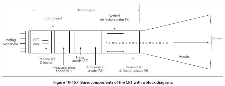
Frequency Measurement/Oscilloscope The oscilloscope is by far one of the more useful electronic measurements available. The viewing capabilities of the oscilloscope make it possible to see and quantify various waveform characteristics such as phase relationships, amplitudes, and durations. While oscilloscopes come in a variety of configurations and presentations, the basic operation is typically the same. Most oscilloscopes in general bench or shop applications use a cathode-ray tube (CRT), which is the device or screen that displays the waveforms. The CRT is a vacuum instrument that contains an electron gun, which emits a very narrow and focused beam of electrons. A phosphorescent coat applied to the back of the screen forms the screen. The beam is electronically aimed and accelerated so that the electron beam strikes the screen. When the electron beam strikes the screen, light is emitted at the point of impact. Figure 10-157 shows the basic components of the CRT with a block diagram.
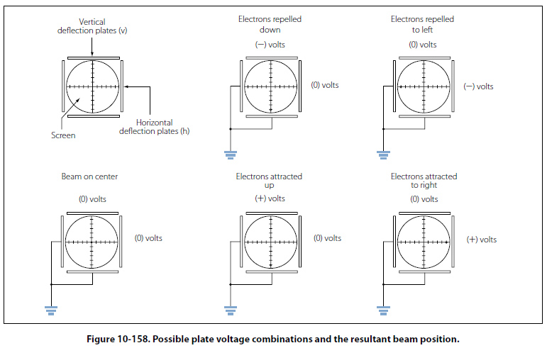
The heated cathode emits electrons. The magnitude of voltage on the control grid determines the actual flow of electrons and thus controls the intensity of the electron beam. The acceleration anodes increase the speed of the electrons, and the focusing anode narrows the beam down to a fine point. The surface of the screen is also an anode and will assist in the acceleration of the electron beam. The purpose of the vertical and horizontal deflection plates is to bend the electron beam and position it to a specific point of the screen. Figure 10-158 illustrates how the deflection plates are used to position the beam on the screen.
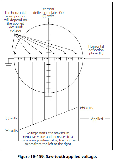
By providing a neutral or zero voltage to a deflection plate, the electron beam will be unaffected. By applying a negative voltage to a plate, the electron beam with be repelled and driven away from the plate. Finally, by applying a positive voltage, the electron beam will be drawing to the plate. Figure 10-158 provides a few possible plate voltage combinations and the resultant beam position. Horizontal Deflection To get a visual representation of the input signal, an internally generated saw-tooth voltage is generated and then applied to the horizontal deflection plates. Figure 10-159 illustrates that the saw-tooth is a pattern of voltage applied, which begins at a negative voltage and increases at a constant rate to a positive voltage.
This applied varying voltage will draw or trace the electron beam from the far left of the screen to the far right side of the screen. The resulting display is a straight line, if the sweep rate is fast enough. This saw-tooth applied voltage is a repetitive signal so that the beam is repeatedly swept across the tube. The rate at which the saw-tooth voltage goes from negative to positive is determined by the frequency. This rate then establishes the sweep rate of the beam. When the saw-tooth reaches the end of its sweep from left to right, the beam then rapidly returns to the left side and is ready to make another sweep. During this time, the electron beam is stopped or blanked out and does not produce any kind of a trace. This period of time is called flyback. |
| ©AvStop Online Magazine Contact Us Return To Books |