![]()
|
|
||
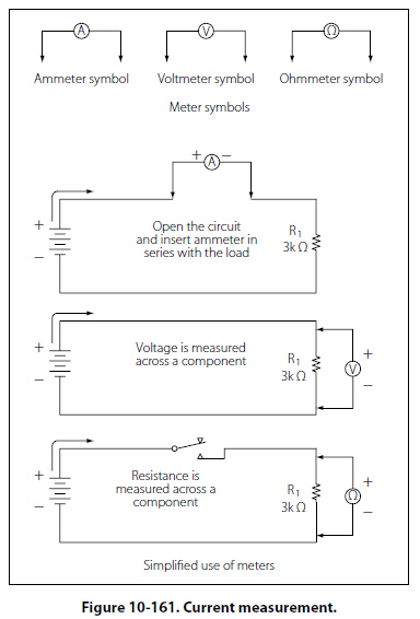
Current Measurement Current is measured with the ammeter connected in the current path by opening or breaking the circuit and inserting the meter in series as shown in Figure 10-161.
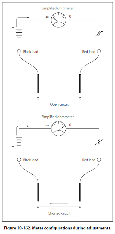
Standard practice is for the red meter lead to be installed in the positive (+) jack and the black meter lead to be installed in the negative meter jack (-). The positive side of the meter is connected towards the positive voltage source. Ideally, the meter should not alter the current and influence the circuit and the measurements. However, the meter does have some effect because of its internal resistance that is connected with the rest of the circuit in series. The resistance is rather small and for most practical purposes, this can be neglected. Checking Resistance in a Circuit The ohmmeter is used to measure the resistance. In its more basic form, the ohmmeter consists of a variable resistor in series with a meter movement and a voltage source. The meter must first be adjusted before use. Refer to Figure 10-162 for meter configurations during adjustments.
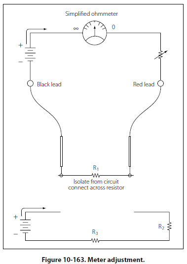
When the meter leads are not connected (open), the needle will point to the full left-hand position, indicating infinite resistance or and open circuit. With the lead placed together, the circuit is shorted as shown with the meter needle to the full right-hand position. When a connection is made, the internal battery is allowed to produce a current through the movement coil, causing a deflection of the needle in proportion to the value of the external resistance. In this case, the resistance is zero because the leads are shorted. The purpose of the variable resistor in the meter is to adjust the current so that the pointer will read exactly zero when the leads are shorted. This is needed because as the battery continues to be used, the voltage will change, thus requiring an adjustment. The meter should be “zeroed" before each use. To check the value of a resistor, the resistor must be disconnected from the circuit. This will prevent any possible damage to the ohmmeter, and it will prevent the possibility of any inaccurate readings due to the circuit being in parallel with the resistor in question. [Figure 10-163]
|
| ©AvStop Online Magazine Contact Us Return To Books |