![]()
|
|
||
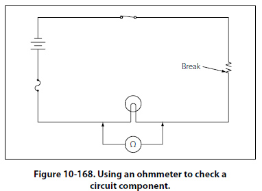
Tracing Opens with the Ohmmeter A simplified circuit as shown in Figures 10-168 and 10-169 illustrates how to locate an open in a series circuit using the ohmmeter. A general rule to keep in mind when troubleshooting with an ohmmeter is: when an ohmmeter is properly connected across a circuit component and a resistance reading is obtained, the component has continuity and is not open.
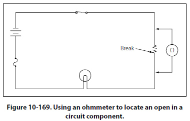
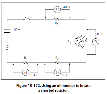
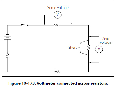
When an ohmmeter is used, the circuit component to be tested must be isolated and the power source removed from the circuit. In this case, as shown in Figure 10-168, these requirements can be met by opening the circuit switch. The ohmmeter is zeroed and across all good components will be zero. The voltage drop across the open component will equal the total voltage across the series combination. This condition happens because the open component will prevent current to pass through the series circuit. With there being no current, there can be no voltage drop across any of the good components. Because the current is zero, it can be determined by Ohm’s law that E = IR = 0 volts across a component. The voltage is the same on both places across (in parallel with) the lamp. In this testing configuration, some value of resistance is read indicating that the lamp is in good condition and is not the source of the open in the circuit. Now the technician should move to the resistor and place the ohmmeter probe across it as shown in Figure 10-169. When the ohmmeter is connected across the open resistor, it indicates infinite resistance, or a discontinuity. Thus, the circuit open has now been located. Troubleshooting the Shorting Faults in Series Circuit An open fault can cause a component or system not to work, which can be critical and hazardous. A shorting fault can potentially be more of a severe nature than the open type of fault. A short circuit, or “short," will cause the opposite effect. A short across a series circuit produces a greater than normal current flow. Faults of this type can develop slowly when a wire bundle is not properly secured and is allowed to chafe against the airframe structure or other systems such as hydraulic lines. Shorts can also occur due to a careless technician using incorrect hardware when installing an interior. If screws that are too long are used to install trim, it is possible to penetrate a wire bundle immediately causing numerous shorts. Worse yet, are the shorts that are not immediately seen but “latent" and do not show symptoms until the aircraft is in service. Another point to keep in mind is when closing panels. Wires can become pinched between the panel and the airframe causing either a short or a latent, intermittent short. The simplified circuit, shown in Figures 10-170 through 10-172, and Figure 10-173 will be used to illustrate troubleshooting a short in a series circuit.
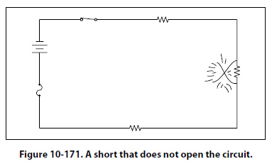
In Figure 10-170, a circuit is designed to light a lamp. A resistor is connected in the circuit to limit current flow. If the resistor is shorted, as shown in the illustration, the current flow will increase and the lamp will become brighter. If the applied voltage were high enough, the lamp would burn out, but in this case the fuse would protect the lamp by opening first. Usually a short circuit will produce an open circuit by either blowing (opening) the fuse or burning out a circuit component. But in some circuits, such as that illustrated in Figure 10-171, there may be additional resistors which will not allow one shorted resistor to increase the current flow enough to blow the fuse or burn out a component. Thus, with one resistor shorted out, the circuit will still function since the power dissipated by the other resistors does not exceed the rating of the fuse. |
| ©AvStop Online Magazine Contact Us Return To Books |