![]()
|
|
||
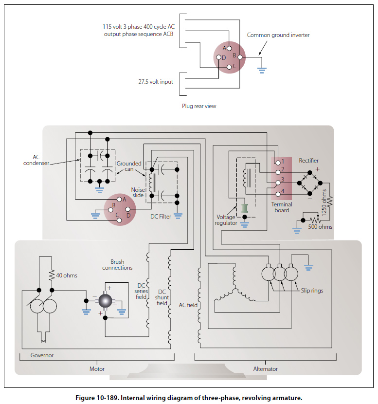
Inverters An inverter is used in some aircraft systems to convert a portion of the aircraft’s DC power to AC. This AC is used mainly for instruments, radio, radar, lighting, and other accessories. These inverters are usually built to supply current at a frequency of 400 cps, but some are designed to provide more than one voltage; for example, 26 volt AC in one winding and 115 volts in another. There are two basic types of inverters: the rotary and the static. Either type can be single phase or multiphase. The multiphase inverter is lighter for the same power rating than the single phase, but there are complications in distributing multiphase power and in keeping the loads balanced. Rotary Inverters There are many sizes, types, and configurations of rotary inverters. Such inverters are essentially AC generators and DC motors in one housing. The generator field, or armature, and the motor field, or armature, are mounted on a common shaft that will rotate within the housing. One common type of rotary inverter is the permanent magnet inverter. Permanent Magnet Rotary Inverter A permanent magnet inverter is composed of a DC motor and a permanent magnet AC generator assembly. Each has a separate stator mounted within a common housing. The motor armature is mounted on a rotor and connected to the DC supply through a commutator and brush assembly. The motor field windings are mounted on the housing and connected directly to the DC supply. A permanent magnet rotor is mounted at the opposite end of the same shaft as the motor armature, and the stator windings are mounted on the housing, allowing AC to be taken from the inverter without the use of brushes. Figure 10-188 shows an internal wiring diagram for this type of rotary inverter. The generator rotor has six poles, magnetized to provide alternate north and south poles about its circumference. When the motor field and armature are excited, the rotor will begin to turn. As the rotor turns, the permanent magnet will rotate within the AC stator coils, and the magnetic flux developed by the permanent magnets will be cut by the conductors in the AC stator coils. An AC voltage will be produced in the windings whose polarity will change as each pole passes the windings. This type inverter may be made multiphase by placing more AC stator coils in the housing in order to shift the phase the proper amount in each coil. As the name of the rotary inverter indicates, it has a revolving armature in the AC generator section. The illustration in Figure 10-189 shows the diagram of a revolving armature, three phase inverter.
The DC motor in this inverter is a four pole, compound wound motor. The four field coils consist of many turns of fine wire, with a few turns of heavy wire placed on top. The fine wire is the shunt field, connected to the DC source through a filter and to ground through a centrifugal governor. The heavy wire is the series field, which is connected in series with the motor armature. The centrifugal governor controls the speed by shunting a resistor that is in series with the shunt field when the motor reaches a certain speed. The alternator is a three-phase, four-pole, star-connected AC generator. The DC input is supplied to the generator field coils and connected to ground through a voltage regulator. The output is taken off the armature through three slip rings to provide three-phase power. The inverter would be a single-phase inverter if it had a single armature winding and one slip ring. The frequency of this type unit is determined by the speed of the motor and the number of generator poles. |
| ©AvStop Online Magazine Contact Us Return To Books |