![]()
|
|
||
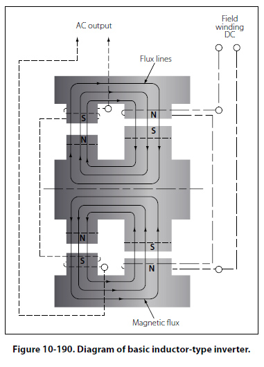
Inductor-Type Rotary Inverter Inductor-type inverters use a rotor made of soft iron laminations with grooves cut laterally across the surface to provide poles that correspond to the number of stator poles, as illustrated in Figure 10-190. The field
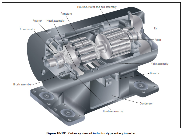
coils are wound on one set of stationary poles and the AC armature coils on the other set of stationary poles. When DC is applied to the field coils, a magnetic field is produced. The rotor turns within the field coils and, as the poles on the rotor align with the stationary poles, a low reluctance path for flux is established from the field pole through the rotor poles to the AC armature pole and through the housing back to the field pole. In this circumstance, there will be a large amount of magnetic flux linking the AC coils. When the rotor poles are between the stationary poles, there is a high reluctance path for flux, consisting mainly of air; then, there will be a small amount of magnetic flux linking the AC coils. This increase and decrease in flux density in the stator induces an alternating current in the AC coils. The number of poles and the speed of the motor determine the frequency of this type of inverter. The DC stator field current controls the voltage. A cutaway view of an inductor-type rotary inverter is shown in Figure 10-191.
Figure 10-192 is a simplified diagram of a typical aircraft AC power distribution system, utilizing a main and a standby rotary inverter system.
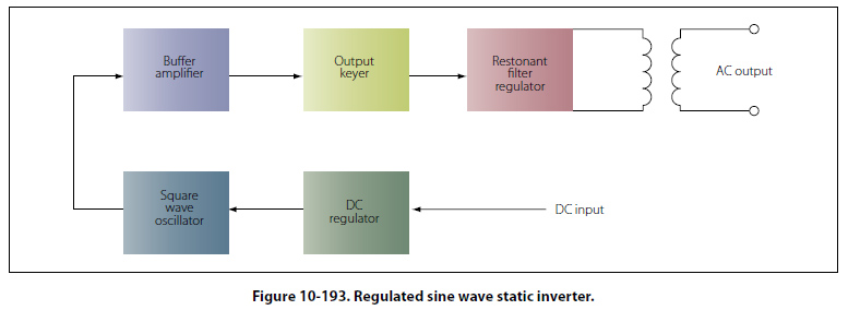
Static Inverters In many applications where continuous DC voltage must be converted to alternating voltage, static inverters are used in place of rotary inverters or motor generator sets. The rapid progress made by the semiconductor industry is extending the range of applications of such equipment into voltage and power ranges that would have been impractical a few years ago. Some such applications are power supplies for frequency sensitive military and commercial AC equipment, aircraft emergency AC systems, and conversion of wide frequency range power to precise frequency power. The use of static inverters in small aircraft also has increased rapidly in the last few years, and the technology has advanced to the point that static inverters are available for any requirement filled by rotary inverters. For example, 250 VA emergency AC supplies operated from aircraft batteries are in production, as are 2,500 VA main AC supplies operated from a varying frequency generator supply. This type of equipment has certain advantages for aircraft applications, particularly the absence of moving parts and the adaptability to conduction cooling. Static inverters, referred to as solid-state inverters, are manufactured in a wide range of types and models, which can be classified by the shape of the AC output waveform and the power output capabilities. One of the most commonly used static inverters produces a regulated sine wave output. A block diagram of a typical regulated sine wave static inverter is shown in Figure 10-193. This inverter converts a low DC voltage into higher AC voltage. The AC output voltage is held to a very small voltage tolerance, a typical variation of less than 1 percent with a full input load change. Output taps are normally provided to permit selection of various voltages; for example, taps may be provided for a 105, 115, and 125 volt AC outputs. Frequency regulation is typically within a range of one cycle for a 0 –100 percent load change.
Variations of this type of static inverter are available, many of which provide a square wave output. Since static inverters use solid-state components, they are considerably smaller, more compact, and much lighter in weight than rotary inverters. Depending on the output power rating required, static inverters that are no larger than a typical airspeed indicator can be used in aircraft systems. Some of the features of static inverters are:
Static inverters are commonly used to provide power for such frequency sensitive instruments as the attitude gyro and directional gyro. They also provide power for autosyn and magnesyn indicators and transmitters, rate gyros, radar, and other airborne applications. Figure 10-194 is a schematic of a typical small jet aircraft auxiliary battery system. It shows the battery as input to the inverter, and the output inverter circuits to various subsystems.
|
| ©AvStop Online Magazine Contact Us Return To Books |