![]()
|
|
||
CHAPTER 2. Aircraft Drawings
The exchange of ideas is essential to everyone, regardless of his or her vocation or position. Usually, this exchange is carried on by the oral or written word; but under some conditions, the use of these alone is impractical. Industry discovered that it could not depend entirely upon written or spoken words for the exchange of ideas because misunderstanding and misinterpretation arose frequently. A written description of an object can be changed in meaning just by misplacing a comma; the meaning of an oral description can be completely changed by the use of a wrong word. To avoid these possible errors, industry uses drawings to describe objects. For this reason, drawing is the draftsman’s language. Drawing, as we use it, is a method of conveying ideas concerning the construction or assembly of objects. This is done with the help of lines, notes, abbreviations, and symbols. It is very important that the aviation mechanic who is to make or assemble the object understand the meaning of the different lines, notes, abbreviations, and symbols that are used in a drawing. (See especially the “Lines and Their Meanings" section of this chapter.) Computer Graphics From the early days of aviation, development of aircraft, aircraft engines, and other components relied heavily on aircraft drawings. For most of the 20th century, drawings were created on a drawing “board" with pen or pencil and paper. However, with the introduction and advancement of computers in the later decades of the 20th century, the way drawings are created changed dramatically. Computers were used not only to create drawings, but they were being used to show items in “virtual reality," from any possible viewing angle. Further development saw computer software programs with the capability of assembling separately created parts to check for proper fit and possible interferences. Additionally, with nearly instantaneous information sharing capability through computer networking and the Internet, it became much easier for designers to share their work with other designers and manufacturers virtually anytime, anywhere in the world. Using new computer controlled manufacturing techniques, it literally became possible to design a part and have it precisely manufactured without ever having it shown on paper. New terms and acronyms became commonplace. The more common of these terms are:
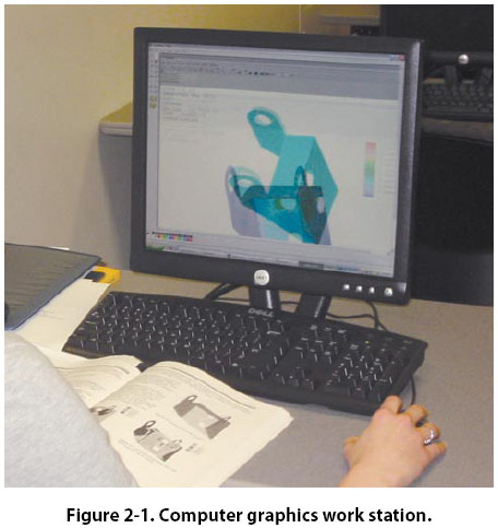
As computer hardware and software continue to evolve, there continues to be a greater amount of CAE done in less time at lower cost. In addition to product design, some of the other uses of CAE are product analysis, assembly, simulations and maintenance information. [Figure 2-1]
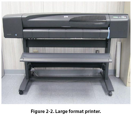
Purpose and Function of Aircraft Drawings Drawings and prints are the link between the engineers who design an aircraft and the workers who build, maintain, and repair it. A print may be a copy of a working drawing for an aircraft part or group of parts, or for a design of a system or group of systems. They are made by placing a tracing of the drawing over a sheet of chemically treated paper and exposing it to a strong light for a short period of time. When the exposed paper is developed, it turns blue where the light has penetrated the transparent tracing. The inked lines of the tracing, having blocked out the light, show as white lines on a blue background. Other types of sensitized paper have been developed; prints may have a white background with colored lines or a colored background with white lines. Drawings created using computers may be viewed as they appear on the computer monitor, or they may be printed out in “hard copy" by use of an ink jet or laser printer. Larger drawings may be printed by use of a plotter or large format printer. Large printers can print drawings up to 42 inches high with widths up to 600 inches by use of continuous roll paper. [Figure 2-2]
|
| ©AvStop Online Magazine Contact Us Return To Books |