![]()
|
|
||
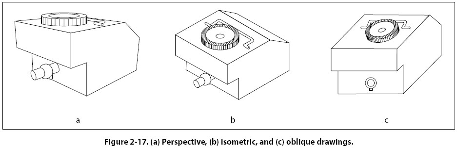
Pictorial Drawings A pictorial drawing [Figure 2-16] is similar to a photograph. It shows an object as it appears to the eye, but it is not satisfactory for showing complex forms and shapes. Pictorial drawings are useful in showing the general appearance of an object and are used extensively with orthographic projection drawings. Pictorial drawings are used in maintenance, overhaul, and part numbers. Three types of pictorial drawings are used frequently by aircraft engineers and technicians: (1) perspective, (2) isometric, and (3) oblique.
Perspective Drawings A perspective view [Figure 2-17(a)] shows an object as it appears to an observer. It most closely resembles the way an object would look in a photograph. Because of perspective, some of the lines of an object are not parallel and therefore the actual angles and dimensions are not accurate. Isometric Drawings An isometric view [Figure 2-17(b)] uses a combination of the views of an orthographic projection and tilts the object forward so that portions of all three views can be seen in one view. This provides the observer with a three-dimensional view of the object. Unlike a perspective drawing where lines converge and dimensions are not true, lines in an isometric drawing are parallel and dimensioned as they are in an orthographic projection.
Oblique Drawings An oblique view [Figure 2-17(c)] is similar to an isometric view except for one distinct difference. In an oblique drawing, two of the three drawing axes are always at right angles to each other. Exploded View Drawings An exploded view drawing is a pictorial drawing of two or more parts that fit together as an assembly. The view shows the individual parts and their relative position to the other parts before they are assembled. Diagrams A diagram may be defined as a graphic representation of an assembly or system, indicating the various parts and expressing the methods or principles of operation. There are many types of diagrams; however, those with which the aviation mechanic will be concerned during the performance of his or her job may be grouped into four classes or types: (1) installation, (2) schematic, (3) block, and (4) wiring diagrams. Installation Diagrams
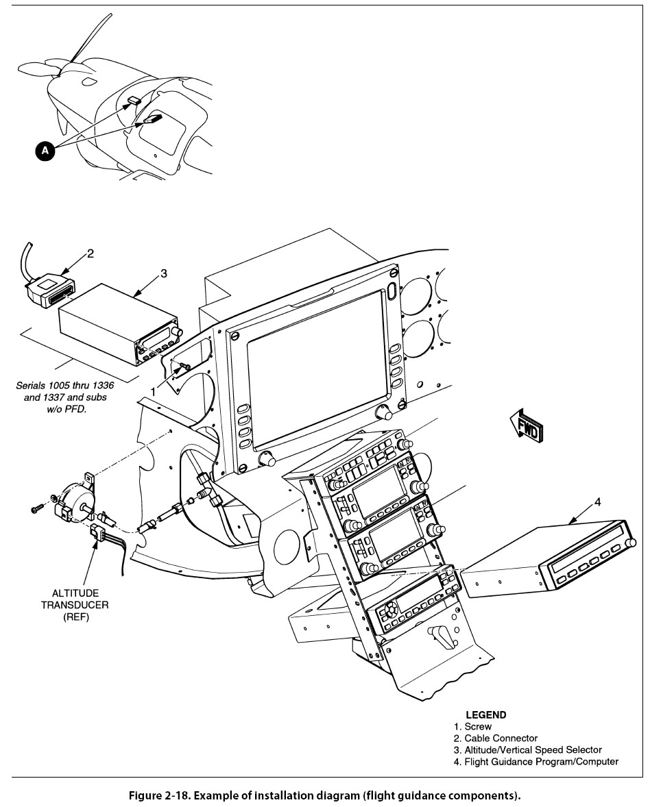
Figure 2-18 is an example of an installation diagram. This is a diagram of the installation of the flight guidance control components of an aircraft. It identifies each of the components in the systems and shows their location in the aircraft. Each number (1, 2, 3, and 4) on the detail shows the location of the individual flight guidance system components within the cockpit of the aircraft. Installation diagrams are used extensively in aircraft maintenance and repair manuals, and are invaluable in identifying and locating components and understanding the operation of various systems. |
| ©AvStop Online Magazine Contact Us Return To Books |