![]()
|
|
||
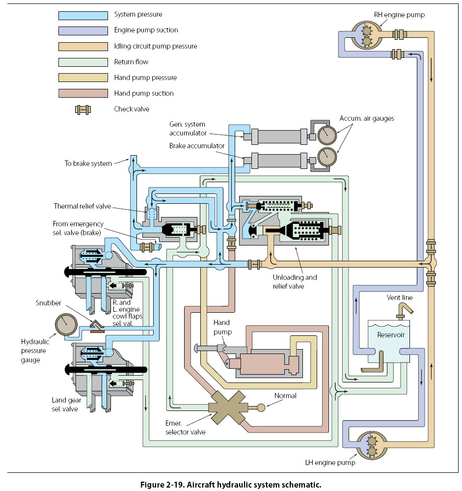
Schematic Diagrams Schematic diagrams do not indicate the location of individual components in the aircraft, but locate components with respect to each other within the system. Figure 2-19 illustrates a schematic diagram of an aircraft hydraulic system. The hydraulic pressure gauge is not necessarily located above the landing gear selector valve in the aircraft. It is, however, connected to the pressure line that leads to the selector valve.
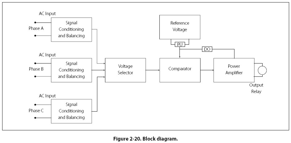
Schematic diagrams of this type are used mainly in troubleshooting. Note that each line is coded for ease of reading and tracing the flow. Each component is identified by name, and its location within the system can be ascertained by noting the lines that lead into and out of the unit. Schematic diagrams and installation diagrams are used extensively in aircraft manuals. Block Diagrams Block diagrams [Figure 2-20] are used to show a simplified relationship of a more complex system of components. Individual components are drawn as a rectangle (block) with lines connecting it to other components (blocks) that it interfaces with during operation.
|
| ©AvStop Online Magazine Contact Us Return To Books |