![]()
|
|
||
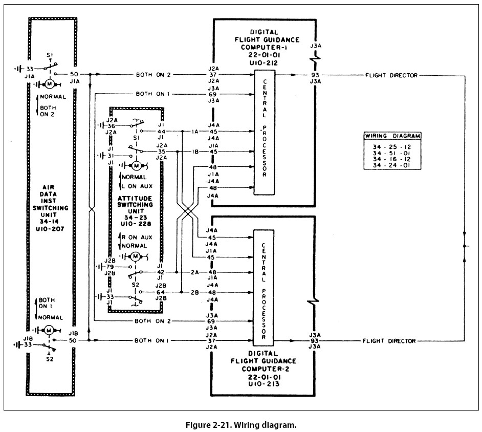
Wiring Diagrams Wiring diagrams [Figure 2-21] show the electrical wiring and circuitry, coded for identification, of all the electrical appliances and devices used on aircraft. These diagrams, even for relatively simple circuits, can be quite complicated. For technicians involved with electrical repairs and installations, a thorough knowledge of wiring diagrams and electrical schematics is essential.
Flowcharts Flowcharts are used to illustrate a particular sequence, or flow of events. Troubleshooting Flowchart Troubleshooting flowcharts are frequently used for the detection of faulty components. They often consist of a series of yes or no questions. If the answer to a question is yes, one course of action is followed. If the answer is no, a different course of action is followed. In this simple manner, a logical solution to a particular problem may be achieved. Another type of flowchart, developed specifically for analysis of digitally controlled components and systems, is the logic flowchart. Logic Flowchart
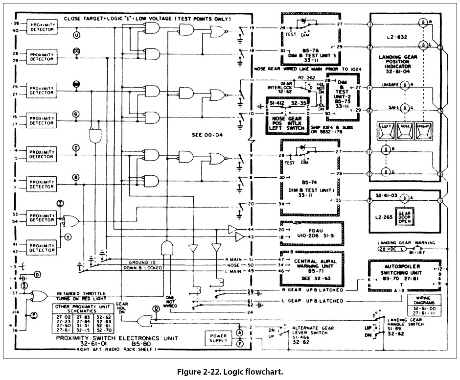
A logic flowchart [Figure 2-22] uses standardized symbols to indicate specific types of logic gates and their relationship to other digital devices in a system. Since digital systems make use of binary mathematics consisting of 1s and 0s, voltage or no voltage, a light pulse or no light pulse, and so forth, logic flowcharts consist of individual components that take an input and provide an output which is either the same as the input or opposite. By analyzing the input or multiple inputs, it is possible to determine the digital output or outputs. |
| ©AvStop Online Magazine Contact Us Return To Books |