![]()
|
|
||
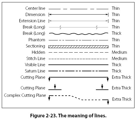
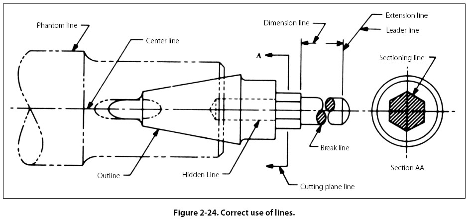
Lines and Their Meanings Every drawing is composed of lines. Lines mark the boundaries, edges, and intersection of surfaces. Lines are used to show dimensions and hidden surfaces and to indicate centers. Obviously, if the same kind of line is used to show all of these variations, a drawing becomes a meaningless collection of lines. For this reason, various kinds of standardized lines are used on aircraft drawings. These are illustrated in Figure 2-23, and their correct uses are shown in Figure 2-24. Most drawings use three widths, or intensities, of lines: thin, medium, or thick. These lines may vary somewhat on different drawings, but there will always be a noticeable difference between a thin and a thick line, with the width of the medium line somewhere between the two.
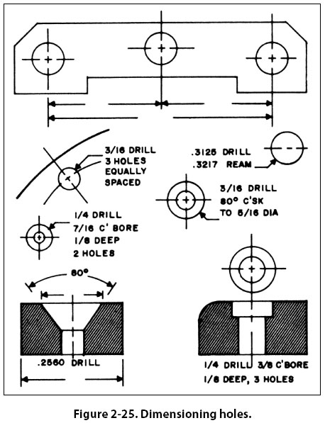
Centerlines Centerlines are made up of alternate long and short dashes. They indicate the center of an object or part of an object. Where centerlines cross, the short dashes intersect symmetrically. In the case of very small circles, the centerlines may be shown unbroken. Dimension Lines A dimension line is a light solid line, broken at the midpoint for insertion of measurement indications, and having opposite pointing arrowheads at each end to show origin and termination of a measurement. They are generally parallel to the line for which the dimension is given, and are usually placed outside the outline of the object and between views if more than one view is shown. All dimensions and lettering are placed so that they will read from left to right. The dimension of an angle is indicated by placing the degree of the angle in its arc. The dimensions of circular parts are always given in terms of the diameter of the circle and are usually marked with the letter D or the abbreviation DIA following the dimension. The dimension of an arc is given in terms of its radius and is marked with the letter R following the dimension. Parallel dimensions are placed so that the longest dimension is farthest from the outline and the shortest dimension is closest to the outline of the object. On a drawing showing several views, the dimensions will be placed upon each view to show its details to the best advantage. In dimensioning distances between holes in an object, dimensions are usually given from center to center rather than from outside to outside of the holes. When a number of holes of various sizes are shown, the desired diameters are given on a leader followed by notes indicating the machining operations for each hole. If a part is to have three holes of equal size, equally spaced, this information is explicitly stated. For precision work, sizes are given in decimals. Diameters and depths are given for counterbored holes. For countersunk holes, the angle of countersinking and the diameters are given. Study the examples shown in Figure 2-25.
The dimensions given for tolerances signifies the amount of clearance allowable between moving parts. A positive allowance is indicated for a part that is to slide or revolve upon another part. A negative allowance is one given for a force fit. Whenever possible, the tolerance and allowances for desired fits conform to those set up in the American Standard for Tolerances, Allowances, and Gauges for Metal Fits. The classes of fits specified in the standard may be indicated on assembly drawings. |
| ©AvStop Online Magazine Contact Us Return To Books |