![]()
|
|
||
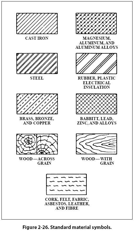
Material Symbols Section line symbols show the kind of material from which the part is to be constructed. The material may not be indicated symbolically if its exact specification is shown elsewhere on the drawing. In this case, the more easily drawn symbol for cast iron is used for the sectioning, and the material specification is listed in the bill of materials or indicated in a note. Figure 2-26 illustrates a few standard material symbols.
Shape Symbols Symbols can be used to excellent advantage when needed to show the shape of an object. Typical shape symbols used on aircraft drawings are shown in Figure 2-27. Shape symbols are usually shown on a drawing as a revolved or removed section.
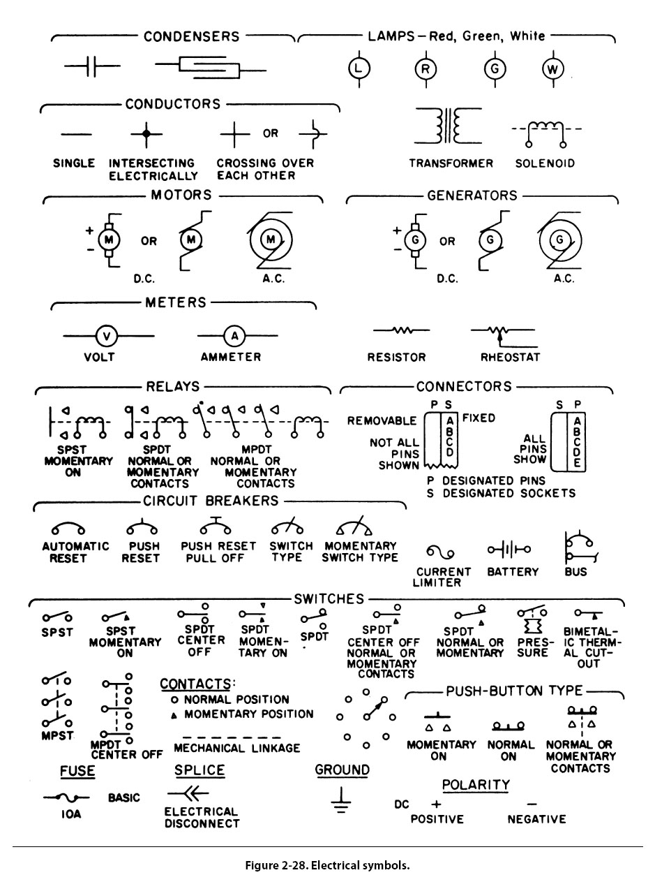
Electrical Symbols Electrical symbols [Figure 2-28] represent various electrical devices rather than an actual drawing of the units. Having learned what the various symbols indicate, it becomes relatively simple to look at an electrical diagram and determine what each unit is, what function it serves, and how it is connected in the system.
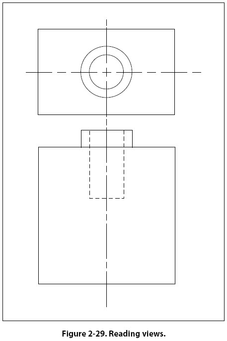
Reading and Interpreting Drawings Aircraft technicians do not necessarily need to be accomplished in making drawings. However, they must have a working knowledge of the information that is to be conveyed to them. They most frequently encounter drawings for construction and assembly of new aircraft and components, during modifications, and for making repairs. A drawing cannot be read all at once any more than a whole page of print can be read at a glance. Both must be read a line at a time. To read a drawing effectively, follow a systematic procedure. Upon opening a drawing, read the drawing number and the description of the article. Next, check the model affected, the latest change letter, and the next assembly listed. Having determined that the drawing is the correct one, proceed to read the illustration(s). In reading a multiview drawing, first get a general idea of the shape of the object by scanning all the views; then select one view for a more careful study. By referring back and forth to the adjacent view, it will be possible to determine what each line represents Each line on a view represents a change in the direction of a surface but another view must be consulted to determine what the change is. For example, a circle on one view may mean either a hole or a protruding boss, as in the top view of the object in Figure 2-29. Looking at the top view, we see two circles; however, the other view must be consulted to determine what each circle represents.
A glance at the other view tells us that the smaller circle represents a hole, and the larger circle represents a protruding boss. In the same way, the top view must be consulted to determine the shape of the hole and the protruding boss. It can be seen from this example that one cannot read a print by looking at a single view when more than one view is given. Two views will not always describe an object and when three views are given, all three must be consulted to be sure the shape has been read correctly. After determining the shape of an object, determine its size. Information on dimensions and tolerances is given so that certain design requirements may be met. Dimensions are indicated by figures either with or without the inch mark. If no inch mark is used, the dimension is in inches. It is customary to give part dimensions and an overall dimension that gives the greatest length of the part. If the overall dimension is missing, it can be determined by adding the separate part dimensions. Drawings may be dimensioned in decimals or fractions. This is especially true in reference to tolerances. Instead of using plus and minus signs for tolerances, many figures give the complete dimension for both tolerances. For example, if a dimension is 2 inches with a plus or minus tolerance of 0.01, the drawing would show the total dimensions as: 2.01 A print tolerance (usually found in the title block) is a general tolerance that can be applied to parts where the dimensions are noncritical. Where a tolerance is not shown on a dimension line, the print tolerance applies. To complete the reading of a drawing, read the general notes and the contents of the material block, check and find the various changes incorporated, and read the special information given in or near views and sections. |
| ©AvStop Online Magazine Contact Us Return To Books |