![]()
|
|
||
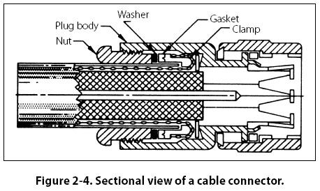
Installation Drawing An installation drawing is one which includes all necessary information for a part or an assembly in the final installed position in the aircraft. It shows the dimensions necessary for the location of specific parts with relation to the other parts and reference dimensions that are helpful in later work in the shop. (See installation drawing at the bottom of Figure 2-3.) Sectional View Drawings A section or sectional view is obtained by cutting away part of an object to show the shape and construction at the cutting plane. The part or parts cut away are shown by the use of section (crosshatching) lines. Types of sections are described in the following paragraphs. Full Section A full section view is used when the interior construction or hidden features of an object cannot be shown clearly by exterior views. For example, Figure 2-4, a sectional view of a coaxial cable connector, shows the internal construction of the connector.
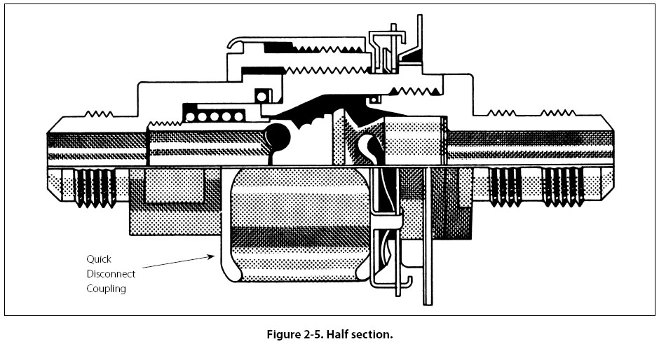
Half Section In a half section, the cutting plane extends only halfway across the object, leaving the other half of the object as an exterior view. Half sections are used to advantage with symmetrical objects to show both the interior and exterior. Figure 2-5 is a half sectional view of a quick disconnect used in aircraft fluid systems.
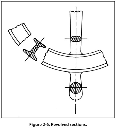
Revolved Section A revolved section drawn directly on the exterior view shows the shape of the cross section of a part, such as the spoke of a wheel. An example of a revolved section is shown in Figure 2-6.
|
| ©AvStop Online Magazine Contact Us Return To Books |