![]()
|
|
||
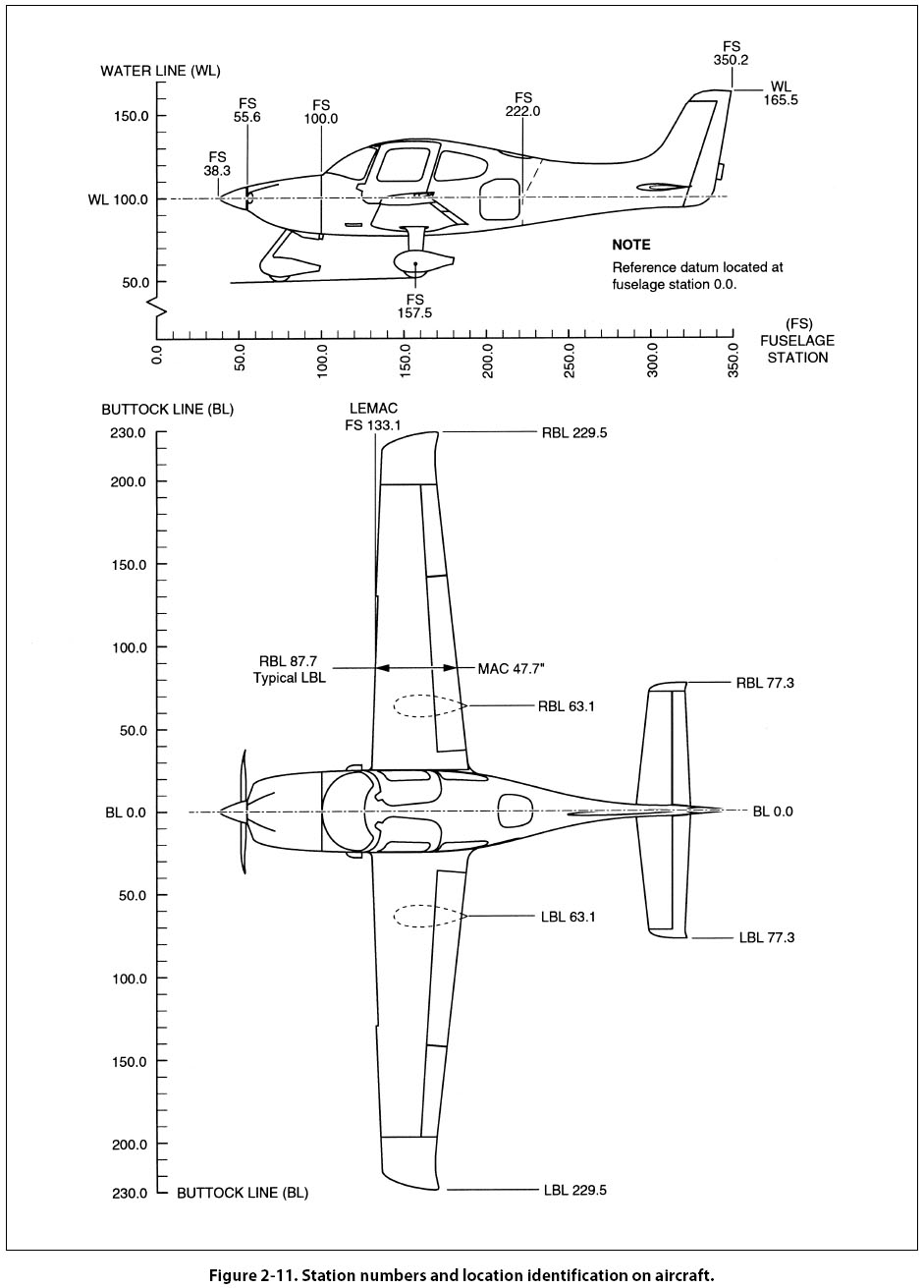
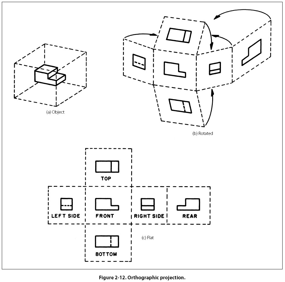
Station Numbers and Location Identification on Aircraft A numbering system is used on large assemblies for aircraft to locate stations such as fuselage stations. Fuselage station 185 indicates a location that is 185 inches from the datum of the aircraft. The measurement is usually taken from the nose or zero station, but in some instances it may be taken from the firewall or some other point chosen by the manufacturer. Just as forward and aft locations on aircraft are made by reference to the datum, locations left and right of the aircraft’s longitudinal axis are made by reference to the buttock line and are called butt stations. Vertical locations on an airplane are made in reference to the waterline. The same station numbering system is used for wing and stabilizer frames. The measurement is taken from the centerline or zero station of the aircraft. Figure 2-11 (on page 2-8) shows use of the fuselage stations (FS), waterline locations (WL), and left and right buttock line locations (RBL and LBL). Allowances and Tolerances When a given dimension on a print shows an allowable variation, the plus (+) figure indicates the maximum, and the minus (-) figure the minimum allowable variation. The sum of the plus and minus allowance figures is called tolerance. For example, using 0.225 + 0.0025 - 0.0005, the plus and minus figures indicate the part will be acceptable if it is not more than 0.0025 larger than the 0.225 given dimension, or not more than 0.0005 smaller than the 0.225 dimension. Tolerance in this example is 0.0030 (0.0025 max plus 0.0005 min). If the plus and minus allowances are the same, you will find them presented as 0.224 ± 0.0025. The tolerance would then be 0.0050. Allowance can be indicated in either fractional or decimal form. When very accurate dimensions are necessary, decimal allowances are used. Fractional allowances are sufficient when precise tolerances are not required. Standard tolerances of -0.010 or -1/32 may be given in the title block of many drawings, to apply throughout the drawing. Finish Marks Finish marks are used to indicate the surface that must be machine finished. Such finished surfaces have a better appearance and allow a closer fit with adjoining parts. During the finishing process, the required limits and tolerances must be observed. Do not confuse machined finishes with those of paint, enamel, chromium plating, and similar coating. Scale Some drawings are made exactly the same size as the drawn part; they have a scale of 1:1. Other scales may be used. However, when drawings are made on a computer, drawing sizes may be easily increased (zoom in) or decreased (zoom out). Some electronic printers have the same capability. Furthermore, when a 1:1 copy of a print is made, the copy size may differ slightly from that of the original. For accurate information, refer to the dimensions shown on the drawing. Application When shown near the title block, application may refer to the aircraft, assembly, sub-assembly or next installation on which the part would be used. Methods of Illustration Applied Geometry Geometry is the branch of mathematics that deals with lines, angles, figures and certain assumed properties in space. Applied geometry, as used in drawing, makes use of these properties to accurately and correctly represent objects graphically. In the past, draftsmen utilized a variety of instruments with various scales, shapes and curves to make their drawings. Today, computer software graphics programs showing drawings provide nearly any scale, shape and curve imaginable, outdating the need for additional instruments. A number of methods are used to illustrate objects graphically. The most common are orthographic projections, pictorial drawings, diagrams, and flowcharts. Orthographic Projection Drawings In order to show the exact size and shape of all the parts of complex objects, a number of views are necessary. This is the system used in orthographic projection. In orthographic projection, there are six possible views of an object, because all objects have six sides—front, top, bottom, rear, right side, and left side. Figure 2-12(a) shows an object placed in a transparent box, hinged at the edges. The projections on the sides of the box are the views as seen looking straight at the object through each side. If the outlines of the object are drawn on each surface and the box opened as shown in (b), then laid flat as shown in (c), the result is a sixview orthographic projection. It is seldom necessary to show all six views to portray an object clearly; therefore, only those views necessary to illustrate the required characteristics of the object
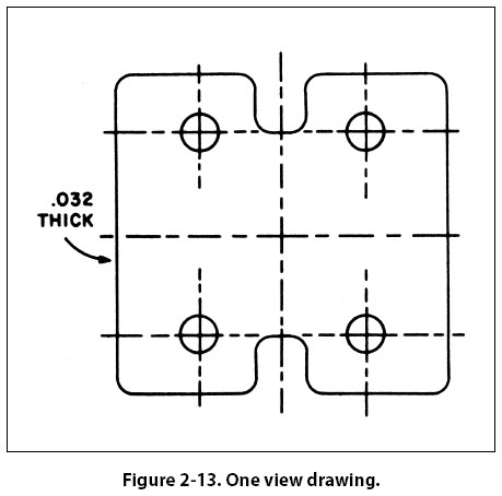
are drawn. One-, two-, and three-view drawings are the most common. Regardless of the number of views used, the arrangement is generally as shown in Figure 2-12, with the front view as principal view. If the right side view is shown, it will be to the right of the front view. If the left side view is shown, it will be to the left of the front view. The top and bottom views, if included, will be shown in their respective positions relative to the front view. One-view drawings are commonly used for objects of uniform thickness such as gaskets, shims, and plates. A dimensional note gives the thickness as shown in Figure 2-13. One-view drawings are also commonly used for cylindrical, spherical, or square parts if all the necessary dimensions can be properly shown in one view.
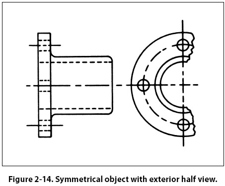
When space is limited and two views must be shown, symmetrical objects are often represented by half views, as illustrated in Figure 2-14.
Aircraft drawings seldom show more than two principal or complete views of an object. Instead, there will be usually one complete view and one or more detail views or sectional views. |
| ©AvStop Online Magazine Contact Us Return To Books |