![]()
|
|
||
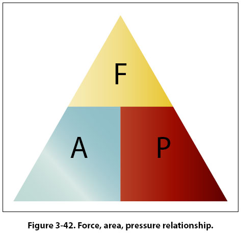
Pascal’s Law The foundations of modern hydraulics and pneumatics were established in 1653 when Pascal discovered that pressure set up in a fluid acts equally in all directions. This pressure acts at right angles to containing surfaces. When the pressure in the fluid is caused solely by the fluid’s height, the pressure against the walls of the container is equal at any given level, but it is not equal if the pressure at the bottom is compared to the pressure half way down. The concept of the pressure set up in a fluid, and how it relates to the force acting on the fluid and the surface area through which it acts, is Pascal’s law. In Figure 3-41, if a piston is placed at the top of the cylinder and an external force pushes down on the piston, additional pressure will be created in the liquid. If the additional pressure is 100 psi, this 100 psi will act equally and undiminished from the top of the cylinder all the way to the bottom. The gauge at the bottom will now read 108.34 psi, and if a gauge were positioned half way down the cylinder, it would read 104.17 psi (100 plus half of 8.34). Pascal’s law, when dealing with the variables of force, pressure, and area, is dealt with by way of the following formula. Force = Pressure × Area In this formula, the force is in units of pounds, the pressure is in pounds per square inch (psi), and the area is in square inches. By transposing the original formula, we have two additional formulas, as follows: Pressure = Force ÷ Area An easy and convenient way to remember the formulas for Pascal’s law, and the relationship between the variables, is with the triangle shown in Figure 3-42. If the variable we want to solve for is covered up, the position of the remaining two variables shows the proper math relationship. For example, if the “A" (area) is covered up, what remains is the “F" on the top and the “P" on the bottom, meaning force divided by pressure.
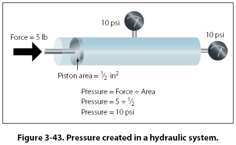
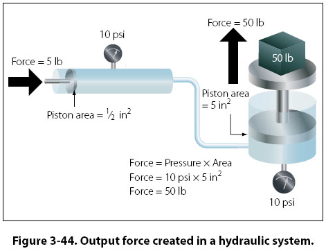
The simple hydraulic system in Figure 3-43 has a 5-lb force acting on a piston with a 1/2-in2 surface area. Based on Pascal’s law, the pressure in the system would be equal to the force applied divided by the area of the piston, or 10 psi. As shown in Figure 3-43, the pressure of 10 psi is present everywhere in the fluid. The hydraulic system in Figure 3-44 is a little more complex than the one in Figure 3-43. In Figure 3-44, the input force of 5 lb is acting on a 1/2-in2 piston, creating a pressure of 10 psi. The input cylinder and piston is connected to a second cylinder, which contains a 5-in2 piston. The pressure of 10 psi created by the
input piston pushes on the piston in the second cylinder, creating an output force of 50 pounds. More often than not, the purpose of a hydraulic system is to generate a large output force, with the input force being much less. In Figure 3-44, the input force is 5 lb and the output force is 50 lb, or 10 times greater. The relationship between the output force and the input force, as discussed earlier in this chapter, is known as mechanical advantage. The mechanical advantage in Figure 3-44 would be 50 divided by 5, or 10. The following formulas can be used to calculate mechanical advantage.
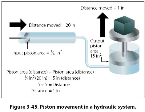
Mechanical Advantage = Force Out ÷ Force In Earlier in this chapter when simple machines, such as levers and gears were discussed, it was identified that no machine allows us to gain work. The same statement holds true for a hydraulic system, that we get no more work out of a hydraulic system than we put in. Since work is equal to force times distance, if we gain force with a hydraulic system, we must lose distance. We only get the same work out, if the system is 100 percent efficient. In order to think about the distance that the output piston will move in response to the movement of the input piston, the volume of fluid displaced must be considered. In the study of geometry, one learns that the volume of a cylinder is equal to the cylinder’s surface area multiplied by its height. So when a piston of 2 in2 moves down in a cylinder a distance of 10 in, it displaces a volume of fluid equal to 20 in3 (2 in2 × 10 in). The 20 in3 displaced by the first piston is what moves over to the second cylinder and causes its piston to move. In a simple two-piston hydraulic system, the relationship between the piston area and the distance moved is shown by the following formula. Input Piston Area (Distance Moved) = Output Piston Area (Distance Moved) In essence, this formula shows that the volume in is equal to the volume out. This concept is shown in Figure 3-45, where a small input piston moves a distance of 20 inches, and the larger output piston only moves a distance of 1 inch.
Example: A two-piston hydraulic system, like that shown in Figure 3-45, has an input piston with an area of 1/4 in2 and an output piston with an area of 15 in2. An input force of 50 lb is applied, and the input piston moves 30 inches. What is the pressure in the system, how much force is generated by the output piston, how far would the output piston move, and what is the mechanical advantage? Pressure = Force ÷ Area Part of understanding Pascal’s law and hydraulics involves utilizing formulas, and recognizing the relationship between the individual variables. Before the numbers are plugged into the formulas, it is often possible to analyze the variables in the system and come to a realization about what is happening. For example, look at the variables in Figure 3-45 and notice that the output piston is 20 times larger than the input piston (5 in2 compared to 1/4 in2). That comparison tells us that the output force will be 20 times greater than the input force, and also that the output piston will only move 1/20 as far. Without doing any formula based calculations, we can conclude that the hydraulic system in question has a mechanical advantage of 20. |
| ©AvStop Online Magazine Contact Us Return To Books |