![]()
|
|
||
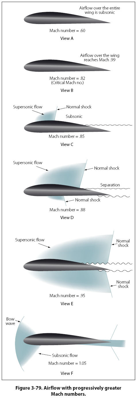
High-Speed Airfoils Transonic flight is the most difficult flight regime for an airplane, because part of the wing is experiencing subsonic airflow and part is experiencing supersonic airflow. For a subsonic airfoil, the aerodynamic center (the point of support) is approximately 25 percent of the way back from the wing leading edge. In supersonic flight, the aerodynamic center moves back to 50 percent of the wing’s chord, causing some significant changes in the airplane’s control and stability. If an airplane designed to fly subsonic, perhaps at a Mach number of 0.80, flies too fast and enters transonic flight, some noticeable changes will take place with respect to the airflow over the wing. Figure 3-79 shows six views of a wing, with each view showing the Mach number getting higher. The scenario for the six views is as follows: A. The Mach number is fairly low, and the entire wing is experiencing subsonic airflow. B. The velocity has reached the critical Mach number, where the airflow over the top of the wing is reaching Mach 1 velocity. C. The velocity has surpassed the critical Mach number, and a normal shock wave has formed on the top of the wing. Some airflow separation starts to occur behind the shock wave. D. The velocity has continued to increase beyond the critical Mach number, and the normal shock wave has moved far enough aft that serious airflow separation is occurring. A normal shock wave is now forming on the bottom of the wing as well. Behind the normal shock waves, the velocity of the air is subsonic and the static pressure has increased. E. The velocity has increased to the point that both shock waves on the wing (top and bottom) have moved to the back of the wing and attached to the trailing edge. Some airflow separation is still occurring. F. The forward velocity of the airfoil is greater than Mach 1, and a new shock wave has formed just forward of the leading edge of the wing. If the wing has a sharp leading edge, the shock wave will attach itself to the sharp edge.
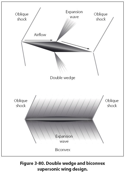
The airfoil shown in Figure 3-79 is not properly designed to handle supersonic airflow. The bow wave in front of the wing leading edge of view F would be attached to the leading edge, if the wing was a double wedge or biconvex design. These two wing designs are shown in Figure 3-80.
|
| ©AvStop Online Magazine Contact Us Return To Books |