![]()
|
|
||
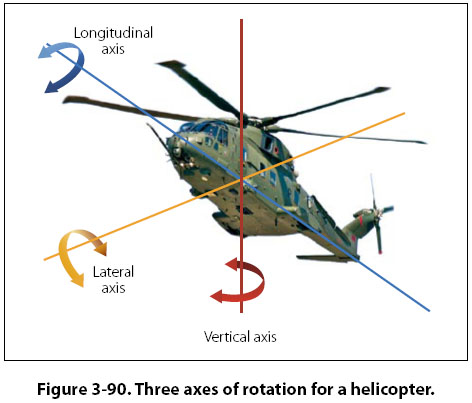
Helicopter Axes of Flight Helicopters, like airplanes, have a vertical, lateral, and longitudinal axis that passes through the helicopter’s center of gravity. Helicopters yaw around the vertical axis, pitch around the lateral axis, and rotate around the longitudinal axis. Figure 3-90 shows the three axes of a helicopter and how they relate to the helicopter’s movement. All three axes will intersect at the helicopter’s center of gravity, and the helicopter pivots around this point. Notice in the figure that the vertical axis passes almost through the center of the main rotor, because the helicopter’s center of gravity needs to be very close to this point.
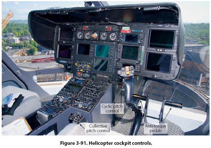
Control Around the Vertical Axis For a single main rotor helicopter, control around the vertical axis is handled by the anti-torque rotor (tail rotor) or from the fan’s airflow on a NOTAR type helicopter. Like in an airplane, rotation around this axis is known as yaw. The pilot controls yaw by pushing on the anti-torque pedals located on the cockpit floor, in the same way the airplane pilot controls yaw by pushing on the rudder pedals. To make the nose of the helicopter yaw to the right, the pilot pushes on the right anti-torque pedal. When viewed from the top, if the helicopter tries to spin in a counterclockwise direction because of the torque of the main rotor, the pilot will also push on the right anti-torque pedal to counteract the main rotor torque. By using the anti-torque pedals, the pilot can intentionally make the helicopter rotate in either direction around the vertical axis. The anti-torque pedals can be seen in Figure 3-91.
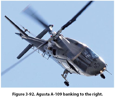
Some helicopters have a vertical stabilizer, such as those shown in Figures 3-90 and 3-92. In forward flight, the vertical stabilizer creates a force that helps counteract the torque of the main rotor, thereby reducing the power needed to drive the anti-torque system located at the end of the tail boom.
Control Around the Longitudinal and Lateral Axes Movement around the longitudinal and lateral axes is handled by the helicopter’s main rotor. In the cockpit, there are two levers that control the main rotor, known as the collective and cyclic pitch controls. The collective pitch lever is on the side of the pilot’s seat, and the cyclic pitch lever is at the front of the seat in the middle. [Figure 3-91] When the collective pitch control lever is raised, the blade angle of all the rotor blades increases uniformly and they create the lift that allows the helicopter to take off vertically. The grip on the end of the collective pitch control is the throttle for the engine, which is rotated to increase engine power as the lever is raised. On many helicopters, the throttle automatically rotates and increases engine power as the collective lever is raised. The collective pitch lever may have adjustable friction built into it, so the pilot does not have to hold upward pressure on it during flight. The cyclic pitch control lever, like the yoke of an airplane, can be pulled back or pushed forward, and can be moved left and right. When the cyclic pitch lever is pushed forward, the rotor blades create more lift as they pass through the back half of their rotation and less lift as they pass through the front half. The difference in lift is caused by changing the blade angle (pitch) of the rotor blades. The pitch change rods that were seen earlier, in Figures 3-82 and 3-83, are controlled by the cyclic pitch lever and they are what change the pitch of the rotor blades. The increased lift in the back either causes the main rotor to tilt forward, the nose of the helicopter to tilt downward, or both. The end result is the helicopter moves in the forward direction. If the cyclic pitch lever is pulled back, the rotor blade lift will be greater in the front and the helicopter will back up. If the cyclic pitch lever is moved to the left or the right, the helicopter will bank left or bank right. For the helicopter to bank to the right, the main rotor blades must create more lift as they pass by the left side of the helicopter. Just the opposite is true if the helicopter is banking to the left. By creating more lift in the back than in the front, and more lift on the left than on the right, the helicopter can be in forward flight and banking to the right. In Figure 3-92, an Agusta A-109 can be seen in forward flight and banking to the right. The rotor blade in the rear and the one on the left are both in an upward raised position, meaning they have both experienced the condition called flap. Some helicopters use a horizontal stabilizer, similar to what is seen on an airplane, to help provide additional stability around the lateral axis. A horizontal stabilizer can be seen on the Agusta A-109 in Figure 3-92. |
| ©AvStop Online Magazine Contact Us Return To Books |