![]()
|
|
||
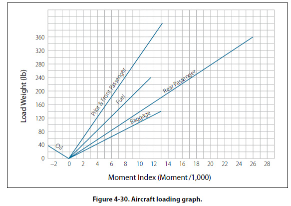
Loading Graphs and CG Envelopes The weight and balance computation system, commonly called the loading graph and CG envelope system, is an excellent and rapid method for determining the CG location for various loading arrangements. This method can be applied to any make and model of aircraft, but is more often seen with small general aviation aircraft. Aircraft manufacturers using this method of weight and balance computation prepare graphs similar to those shown in Figures 4-30 and 4-31 for each make and model aircraft at the time of original certification. The graphs become a permanent part of the aircraft records, and are typically found in the Airplane Flight Manual or Pilot’s Operating Handbook (AFM/POH). These graphs, used in conjunction with the empty weight and empty weight CG data found in the weight and balance report, allow the pilot to plot the CG for the loaded aircraft.
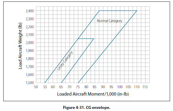
The loading graph illustrated in Figure 4-30 is used to determine the index number (moment value) of any item or weight that may be involved in loading the aircraft. To use this graph, find the point on the vertical scale that represents the known weight. Project a horizontal line to the point where it intersects the proper diagonal weight line (i.e., pilot, copilot, baggage). Where the horizontal line intersects the diagonal, project a vertical line downward to determine the loaded moment (index number) for the weight being added. After the moment for each item of weight has been determined, all weights are added and all moments are added. The total weight and moment is then plotted on the CG envelope. [Figure 4-31] The total weight is plotted on the vertical scale of the graph, with a horizontal line projected out from that point. The total moment is plotted on the horizontal scale of the graph, with a vertical line projected up from that point. Where the horizontal and vertical plot lines intersect on the graph is the center of gravity for the loaded aircraft. If the point where the plot lines intersect falls inside the CG envelope, the aircraft CG is within limits. In Figure 4-31, there are actually two CG envelopes, one for the aircraft in the Normal Category and one for the aircraft in the Utility Category. The loading graph and CG envelope shown in Figures 4-30 and 4-31 are for an airplane with the following specifications and weight and balance data.
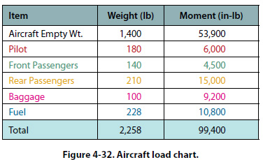
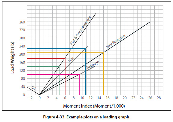
An example of loading the airplane for flight and calculating the total loaded weight and the total loaded moment is shown in Figures 4-32 and 4-33. The use of the loading graph to determine the moment for each of the useful load items is shown in Figure 4-33. The color used for each useful load item in Figure 4-32 matches the color used for the plot on the loading graph.
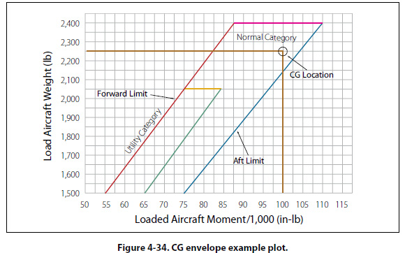
The total loaded weight of the airplane is 2,258 pounds and the total loaded moment is 99,400 in-lb. These two numbers can now be plotted on the CG envelope to see if the airplane is within CG limits. Figure 4-34 shows the CG envelope, with the loaded weight and moment of the airplane plotted. The CG location shown falls
within the normal category envelope, so the airplane is within CG limits for this category. It is interesting to note that the lines that form the CG envelope are actually graphic plots of the forward and aft CG limits. In Figure 4-34, the red line is a graphic plot of the forward limit, and the blue and green lines are graphic plots of the aft limit for the two different categories.
|
| ©AvStop Online Magazine Contact Us Return To Books |