![]()
|
|
||
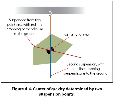
Minimum Fuel There are times when an aircraft will have a weight and balance calculation done, known as an extreme condition check. This is a pencil and paper check in which the aircraft is loaded in as nose heavy or tail heavy a condition as possible to see if the center of gravity will be out of limits in that situation. In a forward adverse check, for example, all useful load in front of the forward CG limit is loaded, and all useful load behind this limit is left empty. An exception to leaving it empty is the fuel tank. If the fuel tank is located behind the forward CG limit, it cannot be left empty because the aircraft cannot fly without fuel. In this case, an amount of fuel is accounted for, which is known as minimum fuel. Minimum fuel is typically that amount needed for 30 minutes of flight at cruise power. For a piston engine powered aircraft, minimum fuel is calculated based on the METO (maximum except take-off) horsepower of the engine. For each METO horsepower of the engine, one-half pound of fuel is used. This amount of fuel is based on the assumption that the piston engine in cruise flight will burn 1 lb of fuel per hour for each horsepower, or 1/2 lb for 30 minutes. The piston engines currently used in small general aviation aircraft are actually more efficient than that, but the standard for minimum fuel has remained the same. Minimum fuel is calculated as follows: For example, if a forward adverse condition check was being done on a piston engine powered twin, with each engine having a METO horsepower of 500, the minimum fuel would be 250 lb (500 METO Hp ÷ 2). For turbine engine powered aircraft, minimum fuel is not based on engine horsepower. If an adverse condition check is being performed on a turbine engine powered aircraft, the aircraft manufacturer would need to supply information on minimum fuel. Tare Weight When aircraft are placed on scales and weighed, it is sometimes necessary to use support equipment to aid in the weighing process. For example, to weigh a tail dragger airplane, it is necessary to raise the tail in order to get the airplane level. To level the airplane, a jack might be placed on the scale and used to raise the tail. Unfortunately, the scale is now absorbing the weight of the jack in addition to the weight of the airplane. This extra weight is known as tare weight, and must be subtracted from the scale reading. Other examples of tare weight are wheel chocks placed on the scales and ground locks left in place on retractable landing gear. Procedures for Weighing an Aircraft General Concepts The most important reason for weighing an aircraft is to find out its empty weight (basic empty weight), and to find out where it balances in the empty weight condition. When an aircraft is to be flown, the pilot in command must know what the loaded weight of the aircraft is, and where its loaded center of gravity is. In order for the loaded weight and center of gravity to be calculated, the pilot or dispatcher handling the flight must first know the empty weight and empty weight center of gravity. Earlier in this chapter it was identified that the center of gravity for an object is the point about which the nose heavy and tail heavy moments are equal. One method that could be used to find this point would involve lifting an object off the ground twice, first suspending it from a point near the front, and on the second lift suspending it from a point near the back. With each lift, a perpendicular line (90 degrees) would be drawn from the suspension point to the ground. The two perpendicular lines would intersect somewhere in the object, and the point of intersection would be the center of gravity. This concept is shown in Figure 4-4, where an irregular shaped object is suspended from two different points. The perpendicular line from the first suspension point is shown in red, and the new suspension point line is shown in blue. Where the red and blue lines intersect is the center of gravity.
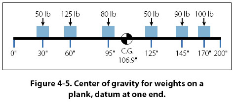
If an airplane were suspended from two points, one at the nose and one at the tail, the perpendicular drop lines would intersect at the center of gravity the same way they do for the object in Figure 4-4. Suspending an airplane from the ceiling by two hooks, however, is clearly not realistic. Even if it could be done, determining where in the airplane the lines intersect would not be possible. A more realistic way to find the center of gravity for an object, especially an airplane, is to place it on a minimum of two scales and to calculate the moment value for each scale reading. In Figure 4-5, there is a plank that is 200" long, with the left end being the datum (zero arm), and 6 weights placed at various locations along the length of the plank. The purpose of Figure 4-5 is to show how the center of gravity can be calculated when the arms and weights for an object are known.
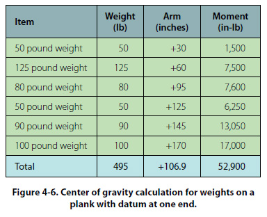
To calculate the center of gravity for the object in Figure 4-5, the moments for all the weights need to be calculated and then summed, and the weights need to be summed. In the four column table in Figure 4-6, the item, weight, and arm are listed in the first three columns, with the information coming from Figure 4-5. The moment value in the fourth column is the product of the weight and arm. The weight and moment columns are summed, with the center of gravity being equal to the total moment divided by the total weight. The arm column is not summed. The number appearing at the bottom of that column is the center of gravity. The calculation would be as shown in Figure 4-6.
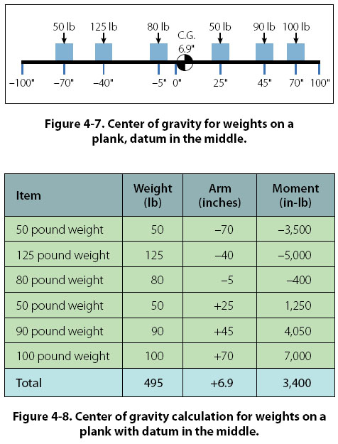
For the calculation shown in Figure 4-6, the total moment is 52,900 in-lb, and the total weight is 495 lb. The center of gravity is calculated as follows: Center of Gravity = Total Moment ÷ Total Weight An interesting characteristic exists for the problem presented in Figure 4-5, and the table showing the center of gravity calculation. If the datum (zero arm) for the object was in the middle of the 200" long plank, with 100" of negative arm to the left and 100" of positive arm to the right, the solution would show the center of gravity to be in the same location. The arm for the center of gravity would not be the same number, but its physical location would be the same. Figure 4-7 and Figure 4-8 show the new calculation.
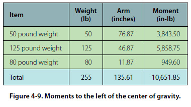
Center of Gravity = Total Moment ÷ Total Weight In Figure 4-7, the center of gravity is 6.9" to the right of the plank’s center. Even though the arm is not the same number, in Figure 4-5 the center of gravity is also 6.9" to the right of center (CG location of 106.9 with the center being 100). Because both problems are the same in these two figures, except for the datum location, the center of gravity must be the same. The definition for center of gravity states that it is the point about which all the moments are equal. We can prove that the center of gravity for the object in Figure 4-7 is correct by showing that the total moments on either side of this point are equal. Using 6.87 as the CG location for slightly greater accuracy, instead of the rounded off 6.9 number, the moments to the left of the CG would be as shown in Figure 4-9.
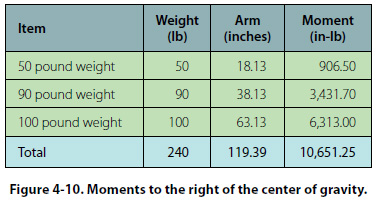
The moments to the right of the CG, as shown in Figure 4-7, would be as shown in Figure 4-10.
Disregarding the slightly different decimal value, the moment in both of the previous calculations is 10,651 in-lb. Showing that the moments are equal is a good way of proving that the center of gravity has been properly calculated. |
| ©AvStop Online Magazine Contact Us Return To Books |