![]()
|
|
||
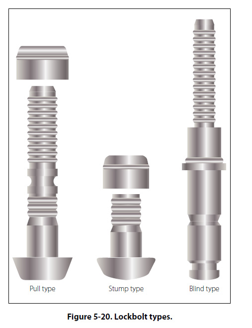
Special-Purpose Bolts Bolts designed for a particular application or use are classified as special-purpose bolts. Clevis bolts, eyebolts, Jo-bolts, and lockbolts are special-purpose bolts. Clevis Bolts The head of a clevis bolt is round and is either slotted to receive a common screwdriver or recessed to receive a crosspoint screwdriver. This type of bolt is used only where shear loads occur and never in tension. It is often inserted as a mechanical pin in a control system. Eyebolt This type of special purpose bolt is used where external tension loads are to be applied. The eyebolt is designed for the attachment of such devices as the fork of a turnbuckle, a clevis, or a cable shackle. The threaded end may or may not be drilled for safetying. Jo-Bolt Jo-bolt is a trade name for an internally threaded threepiece rivet. The Jo-bolt consists of three parts — a threaded steel alloy bolt, a threaded steel nut, and an expandable stainless steel sleeve. The parts are factory preassembled. As the Jo-bolt is installed, the bolt is turned while the nut is held. This causes the sleeve to expand over the end of the nut, forming the blind head and clamping against the work. When driving is complete, a portion of the bolt breaks off. The high shear and tensile strength of the Jo-bolt makes it suitable for use in cases of high stresses where some of the other blind fasteners would not be practical. Jobolts are often a part of the permanent structure of late model aircraft. They are used in areas which are not often subjected to replacement or servicing. (Because it is a three-part fastener, it should not be used where any part, in becoming loose, could be drawn into the engine air intake.) Other advantages of using Jo-bolts are their excellent resistance to vibration, weight saving, and fast installation by one person. Presently, Jo-bolts are available in four diameters: The 200 series, approximately 3/16 inch in diameter; the 260 series, approximately 1/4 inch in diameter; the 312 series, approximately 5/16 inch in diameter; and the 375 series, approximately 3/8 inch in diameter. Jo-bolts are available in three head styles which are: F (flush), P (hex head), and FA (flush millable). Lockbolts Lockbolts are used to attach two materials permanently. They are lightweight and are equal in strength to standard bolts. Lockbolts are manufactured by several companies and conform to Military Standards. Military Standards specify the size of a lockbolt’s head in relation to the shank diameter, plus the alloy used in its construction. The only drawback to lockbolt installations is that they are not easily removable compared to nuts and bolts. The lockbolt combines the features of a high-strength bolt and rivet, but it has advantages over both. The lockbolt is generally used in wing splice fittings, landing gear fittings, fuel cell fittings, longerons, beams, skin splice plates, and other major structural attachments. It is more easily and quickly installed than the conventional rivet or bolt and eliminates the use of lockwashers, cotter pins, and special nuts. Like the rivet, the lockbolt requires a pneumatic hammer or “pull gun" for installation; when installed, it is rigidly and permanently locked in place. Three types of lockbolts are commonly used: the pull type, the stump type, and the blind type. [Figure 5-20]
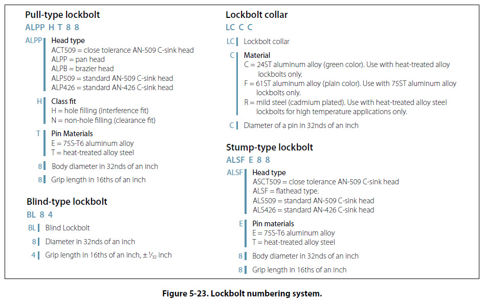
Pull type. Pull-type lockbolts are used mainly in aircraft primary and secondary structures. They are installed very rapidly and have approximately one-half the weight of equivalent AN steel bolts and nuts. A special pneumatic “pull gun" is required to install this type of lockbolt. Installation can be accomplished by one person since bucking is not required. Stump type. Stump-type lockbolts, although they do not have the extended stem with pull grooves, are companion fasteners to pull-type lockbolts. They are used primarily where clearance will not permit installation of the pull-type lockbolt. A standard pneumatic riveting hammer (with a hammer set attached for swaging the collar into the pin locking grooves) and a bucking bar are tools necessary for the installation of stump-type lockbolts. Blind type. Blind-type lockbolts come as complete units or assemblies. They have exceptional strength and sheet pull-together characteristics. Blind lockbolts are used where only one side of the work is accessible and, generally, where it is difficult to drive a conventional rivet. This type of lockbolt is installed in the same manner as the pull-type lockbolt. Common features. Common features of the three types of lockbolts are the annular locking grooves on the pin and the locking collar which is swaged into the pin’s lock grooves to lock the pin in tension. The pins of the pull- and blind-type lockbolts are extended for pull installation. The extension is provided with pulling grooves and a tension breakoff groove. Composition. The pins of pull- and stump-type lockbolts are made of heat-treated alloy steel or high strength aluminum alloy. Companion collars are made of aluminum alloy or mild steel. The blind lockbolt consists of a heat-treated alloy steel pin, blind sleeve and filler sleeve, mild steel collar, and carbon steel washer. Substitution. Alloy steel lockbolts may be used to replace steel high-shear rivets, solid steel rivets, or AN bolts of the same diameter and head type. Aluminum alloy lockbolts may be used to replace solid aluminum alloy rivets of the same diameter and head type. Steel and aluminum alloy lockbolts may also be used to replace steel and 2024T aluminum alloy bolts, respectively, of the same diameter. Blind lockbolts may be used to replace solid aluminum alloy rivets, stainless steel rivets, or all blind rivets of the same diameter. Numbering system. The numbering systems for the various types of lockbolts are explained by the breakouts in Figure 5-23.
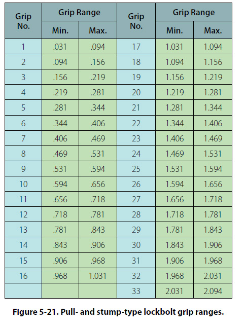
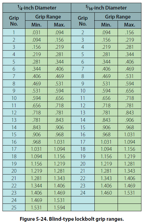
Grip Range. To determine the bolt grip range required for any application, measure the thickness of the material with a hook scale inserted through the hole. Once this measurement is determined, select the correct grip range by referring to the charts provided by the rivet manufacturer. Examples of grip range charts are shown in Figures 5-21 and 5-24.
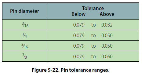
When installed, the lockbolt collar should be swaged substantially throughout the complete length of the collar. The tolerance of the broken end of the pin relative to the top of the collar must be within the dimensions given in Figure 5-22.
When removal of a lockbolt becomes necessary, remove the collar by splitting it axially with a sharp, cold chisel. Be careful not to break out or deform the hole. The use of a backup bar on the opposite side of the collar being split is recommended. The pin may then be driven out with a drift punch. |
| ©AvStop Online Magazine Contact Us Return To Books |