![]()
|
|
||
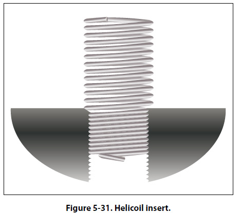
Installation of Nuts, Washers, and Bolts Bolt and Hole Sizes Slight clearances in bolt holes are permissible wherever bolts are used in tension and are not subject to reversal of load. A few of the applications in which clearance of holes may be permitted are in pulley brackets, conduit boxes, lining trim, and miscellaneous supports and brackets. Bolt holes are to be normal to the surface involved to provide full bearing surface for the bolt head and nut, and must not be oversized or elongated. A bolt in such a hole will carry none of its shear load until parts have yielded or deformed enough to allow the bearing surface of the oversized hole to contact the bolt. In this respect, remember that bolts do not become swaged to fill up the holes as do rivets. In cases of oversized or elongated holes in critical members, obtain advice from the aircraft or engine manufacturer before drilling or reaming the hole to take the next larger bolt. Usually, such factors as edge distance, clearance, or load factor must be considered. Oversized or elongated holes in noncritical members can usually be drilled or reamed to the next larger size. Many bolt holes, particularly those in primary connecting elements, have close tolerances. Generally, it is permissible to use the first lettered drill size larger than the normal bolt diameter, except where the AN hexagon bolts are used in light drive fit (reamed) applications and where NAS close tolerance bolts or AN clevis bolts are used. Light drive fits for bolts (specified on the repair drawings as 0.0015 inch maximum clearance between bolt and hole) are required in places where bolts are used in repair, or where they are placed in the original structure. The fit of holes and bolts cannot be defined in terms of shaft and hole diameters; it is defined in terms of the friction between bolt and hole when sliding the bolt into place. A tight drive fit, for example, is one in which a sharp blow of a 12- or 14-ounce hammer is required to move the bolt. A bolt that requires a hard blow and sounds tight is considered to fit too tightly. A light drive fit is one in which a bolt will move when a hammer handle is held against its head and pressed by the weight of the body. Installation Practices Examine the markings on the bolt head to determine that each bolt is of the correct material. It is of extreme importance to use like bolts in replacement. In every case, refer to the applicable Maintenance Instructions Manual and Illustrated Parts Breakdown. Be sure that washers are used under both the heads of bolts and nuts unless their omission is specified. A washer guards against mechanical damage to the material being bolted and prevents corrosion of the structural members. An aluminum alloy washer should be used under the head and nut of a steel bolt securing aluminum alloy or magnesium alloy members. Any corrosion that occurs then attacks the washer rather than the members. Steel washers should be used when joining steel members with steel bolts. Whenever possible, place the bolt with the head on top or in the forward position. This positioning tends to prevent the bolt from slipping out if the nut is accidentally lost. Be certain that the bolt grip length is correct. Grip length is the length of the unthreaded portion of the bolt shank. Generally speaking, the grip length should equal the thickness of the material being bolted together. However, bolts of slightly greater grip length may be used if washers are placed under the nut or the bolt head. In the case of plate nuts, add shims under the plate. Safetying of Bolts and Nuts It is very important that all bolts or nuts, except the self-locking type, be safetied after installation. This prevents them from loosening in flight due to vibration. Methods of safetying are discussed later in this chapter. Repair of Damaged Internal Threads Installation or replacement of bolts is simple when compared to the installation or replacement of studs. Bolt heads and nuts are cut in the open, whereas studs are installed into internal threads in a casting or builtup assembly. Damaged threads on bolts or nuts can be seen and only require replacement of the defective part. If internal threads are damaged, two alternatives are apparent: the part may be replaced or the threads repaired or replaced. Correction of the thread problem is usually cheaper and more convenient. Two methods of repairing are by replacement bushings or helicoils. Replacement Bushings Bushings are usually special material (steel or brass spark plug bushings into aluminum cylinder heads). A material that will resist wear is used where removal and replacement is frequent. The external threads on the bushing are usually coarse. The bushing is installed, a thread lock compound may or may not be used, and staked to prevent loosening. Many bushings have lefthand threads external and right-hand threads internal. With this installation, removal of the bolt or stud (righthand threads) tends to tighten the bushing. Bushings for common installations, such as spark plugs, may be up to 0.040 oversize (in increments of 0.005). Original installation and overhaul shop replacements are shrunk fit: a heated cylinder head and a frozen bushing. Helicoils Helicoils are precision formed screw thread coils of 18-8 stainless steel wire having a diamond shaped cross section.
[Figure 5-31] They form unified coarse or unified fine thread classes 2-band 3B when assembled into (helicoil) threaded holes. The assembled insert accommodates UNJ (controlled radius root) male threaded members. Each insert has a driving tang with a notch to facilitate removal of the tang after the insert is screwed into a helicoil tapped hole. They are used as screw thread bushings. In addition to being used to restore damaged threads, they are used in the original design of missiles, aircraft engines, and all types of mechanical equipment and accessories to protect and strengthen tapped threads in light materials, metals, and plastics, particularly in locations which require frequent assembly and disassembly, and/or where a screw locking action is desired.
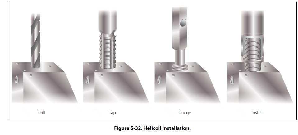
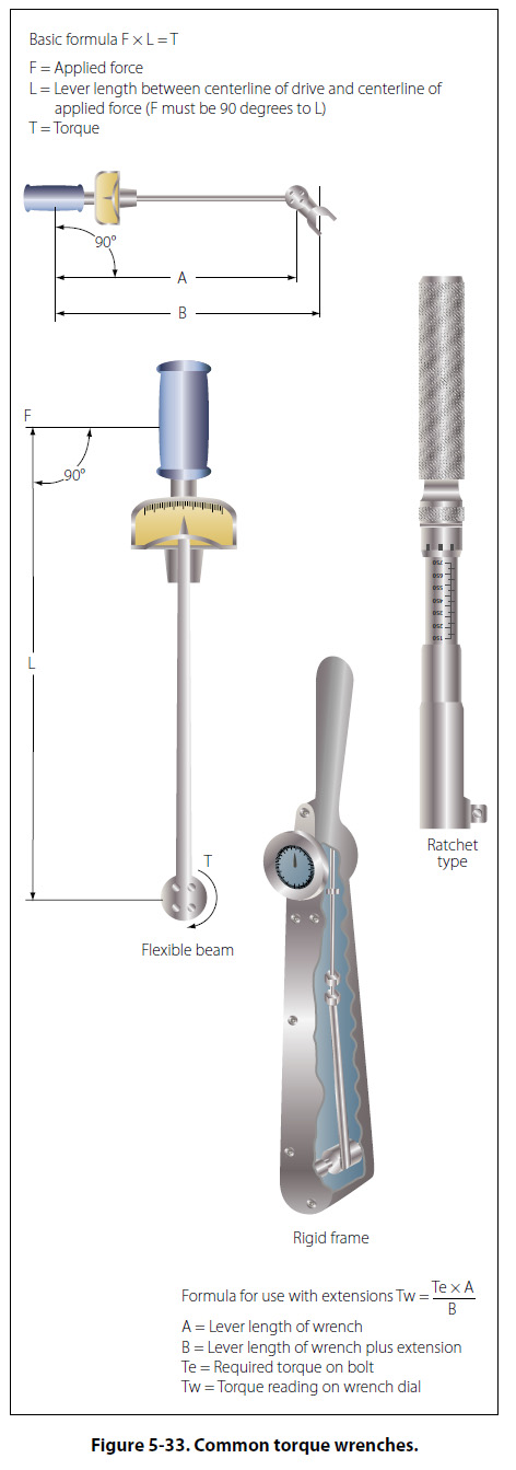
Helicoil installation [Figure 5-32] is a 5 or 6 step operation, depending upon how the last step is classed. Step 1: Determine what threads are damaged. Step 2: (a) New installation of helicoil. Drill out damaged threads to minimum depth specified. (b) Previously installed helicoil. Using proper size extracting tool, place edge of blade in 90° from the edge of the insert. Tap with hammer to seat tool. Turn to left, applying pressure, until insert backs out. Threads are not damaged if insert is properly removed. Step 3: Tap. Use the tap of required nominal thread size. The tapping procedure is the same as standard thread tapping. Tap length must be equal to or exceed the requirement. Step 4: Gauge. Threads may be checked with a helicoil thread gauge. Step 5: Insert assembly. Using proper tool, install insert to a depth that puts end of top coil 1/4 to 1/2 turn below the top surface of the tapped hole. Step 6: Tang breakoff. Select proper breakoff tool. Tangs should be removed from all drilled through holes. In blind holes, the tangs may be removed when necessary if enough hole depth is provided below the tang of the installed insert. These are not to be considered specific instructions on helicoil installation. The manufacturer’s instruction must be followed when making an installation. Helicoils are available for the following threads: unified coarse, unified fine, metric, spark plug, and national taper pipe threads. Fastener Torque Torque and Torque Wrenches As the speed of an aircraft increases, each structural member becomes more highly stressed. It is therefore extremely important that each member carry no more and no less than the load for which it was designed. To distribute the loads safely throughout a structure, it is necessary that proper torque be applied to all nuts, bolts, studs, and screws. Using the proper torque allows the structure to develop its designed strength and greatly reduces the possibility of failure due to fatigue. Torque wrenches. The three most commonly used torque wrenches are the flexible beam, rigid frame, and the ratchet types.
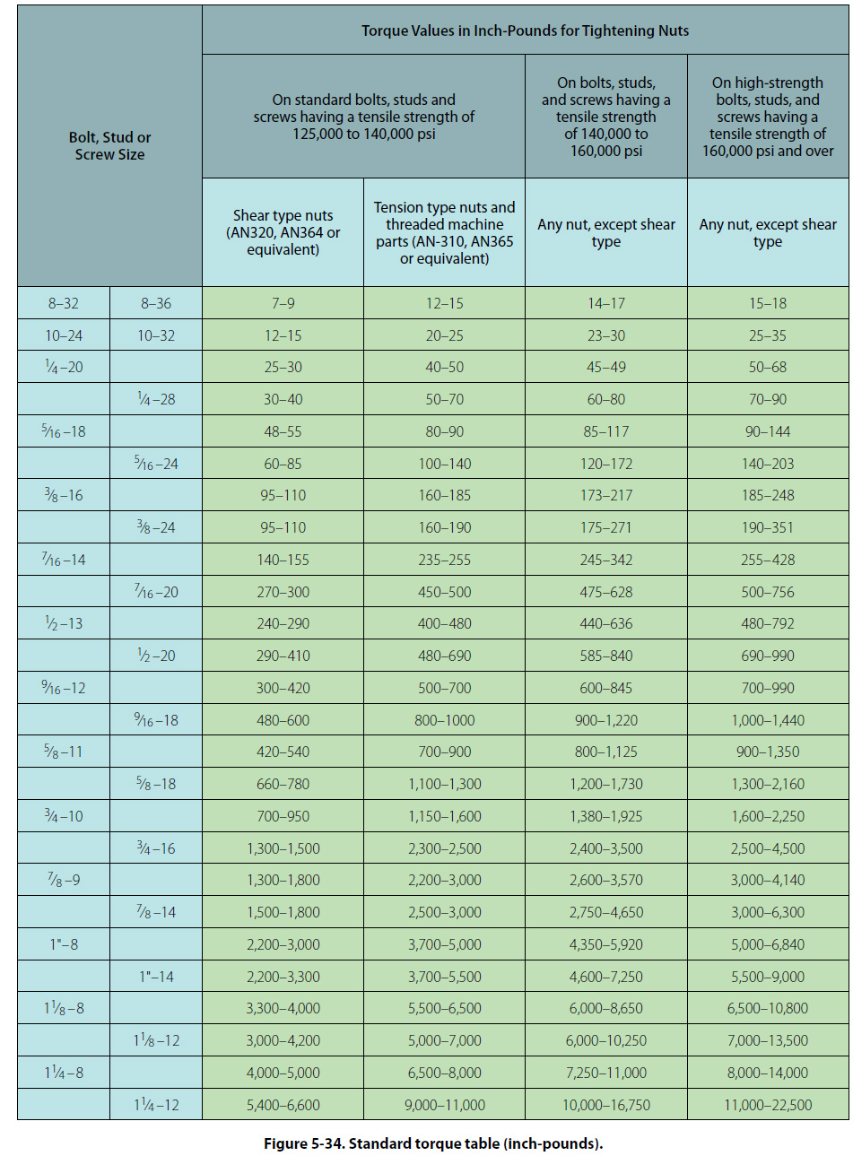
[Figure 5-33] When using the flexible beam and the rigid frame torque wrenches, the torque value is read visually on a dial or scale mounted on the handle of the wrench. To use the ratchet type, unlock the grip and adjust the handle to the desired setting on the micrometer type scale, then relock the grip. Install the required socket or adapter to the square drive of the handle. Place the wrench assembly on the nut or bolt and pull the wrench assembly on the nut or bolt and pull in a clockwise direction with a smooth, steady motion. (A fast or jerky motion will result in an improperly torqued unit.) When the applied torque reaches the torque value indicated on the handle setting, the handle will automatically release or “break" and move freely for a short distance. The release and free travel is easily felt, so there is no doubt about when the torquing process is completed. To assure getting the correct amount of torque on the fasteners, all torque wrenches must be tested at least once a month or more often if necessary. Note: It is not advisable to use a handle length extension on a flexible beam type torque wrench at any time. A handle extension alone has no effect on the reading of the other types. The use of a drive end extension on any type of torque wrench makes the use of the formula mandatory. When applying the formula, force must be applied to the handle of the torque wrench at the point from which the measurements were taken. If this is not done, the torque obtained will be incorrect. Torque Tables. Use the standard torque table as a guide in tightening nuts, studs, bolts, and screws whenever specific torque values are not called out in maintenance procedures. The following rules apply for correct use of the torque table: [Figure 5-34]
1. To obtain values in foot-pounds, divide inchpounds by 12. 2. Do not lubricate nuts or bolts except for corrosionresistant steel parts or where specifically instructed to do so. 3. Always tighten by rotating the nut first if possible. When space considerations make it necessary to tighten by rotating the bolt head, approach the high side of the indicated torque range. Do not exceed the maximum allowable torque value. 4. Maximum torque ranges should be used only when materials and surfaces being joined are of sufficient thickness, area, and strength to resist breaking, warping, or other damage. 5. For corrosion resisting steel nuts, use torque values given for shear type nuts. 6. The use of any type of drive end extension on a torque wrench changes the dial reading required to obtain the actual values indicated in the standard torque range tables. When using a drive end extension, the torque wrench reading must be computed by use of the proper formula, which is included in the handbook accompanying the torque wrench. Cotter Pin Hole Line Up When tightening castellated nuts on bolts, the cotter pin holes may not line up with the slots in the nuts for the range of recommended values. Except in cases of highly stressed engine parts, the nut may not be over torque. Remove hardware and realign the holes. The torque loads specified may be used for all unlubricated cadmium-plated steel nuts of the fine or coarse thread series which have approximately equal number of threads and equal face bearing areas. These values do not apply where special torque requirements are specified in the maintenance manual. If the head end, rather than the nut, must be turned in the tightening operation, maximum torque values may be increased by an amount equal to shank friction, provided the latter is first measured by a torque wrench. |
| ©AvStop Online Magazine Contact Us Return To Books |