![]()
|
|
||
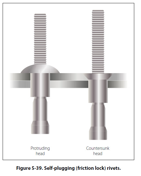
Blind Rivets There are many places on an aircraft where access to both sides of a riveted structure or structural part is impossible, or where limited space will not permit the use of a bucking bar. Also, in the attachment of many nonstructural parts, such as aircraft interior furnishings, fl ooring, deicing boots, and the like, the full strength of solid shank rivets is not necessary. For use in such places, special rivets have been designed which can be bucked from the front. They are sometimes lighter than solid shank rivets, yet amply strong for their intended use. These rivets are produced by several manufacturers and have unique characteristics that require special installation tools, special installation procedures and special removal procedures. That is why they are called special rivets. Because these rivets are often inserted in locations where one head (usually the shop head) cannot be seen, they are also called blind rivets. Mechanically Expanded Rivets Two classes of mechanically expanded rivets are discussed here: (1) Nonstructural. (a) Self-plugging (friction lock) rivets. (b) Pull-thru rivets. (2) Mechanical lock, fl ush fracturing, self plugging rivets. Self-Plugging Rivets (friction lock) The self-plugging (friction lock) blind rivets are manufactured by several companies; the same general basic information about their fabrication, composition, uses, selection, installation, inspection, and removal procedures apply to all of them. Self-plugging (friction lock) rivets are fabricated in two parts: a rivet head with a hollow shank or sleeve, and a stem that extends through the hollow shank. Figure 5-39 illustrates a protruding head and a countersunk head self-plugging rivet produced by one manufacturer. Several events, in their proper sequence, occur when a pulling force is applied to the stem of the rivet: (1) the stem is pulled into the rivet shank; (2) the mandrel portion of the stem forces the rivet shank to expand; and (3) when friction (or pulling action pressure) becomes great enough, it will cause the stem to snap at a breakoff groove on the stem. The plug portion (bottom end of the stem) is retained in the shank of the rivet giving the rivet much greater shear strength than could be obtained from a hollow rivet. Self-plugging (friction lock) rivets are fabricated in two common head styles: (1) a protruding head similar to the MS20470 or universal head, and (2) a 100° countersunk head. Other head styles are available from some manufacturers. The stem of the self-plugging (friction lock) rivet may have a knot or knob on the upper portion, or it may have a serrated portion. [Figure 5-39]
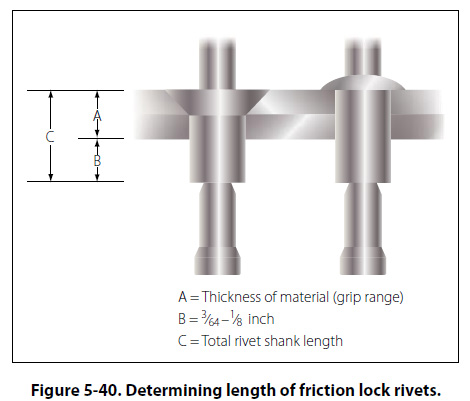
Self-plugging (friction lock) rivets are fabricated from several materials. Rivets are available in the following material combinations: stem 2017 aluminum alloy and sleeve 2117 aluminum alloy; stem 2017 aluminum alloy and sleeve 5056 aluminum alloy; and stem steel and sleeve steel. Self-plugging (friction lock) rivets are designed so that installation requires only one person; it is not necessary to have the work accessible from both sides. The pulling strength of the rivet stem is such that a uniform job can always be assured. Because it is not necessary to have access to the opposite side of the work, selfplugging (friction lock) rivets can be used to attach assemblies to hollow tubes, corrugated sheet, hollow boxes, and so forth. Because a hammering force is not necessary to install the rivet, it can be used to attach assemblies to plywood or plastics. Factors to consider in the selection of the correct rivet for installation are: (1) installation location (2) composition of the material being riveted (3) thickness of the material being riveted (4) strength desired. If the rivet is to be installed on an aerodynamically smooth surface, or if clearance for an assembly is needed, countersunk head rivets should be selected. In other areas where clearance or smoothness is not a factor, the protruding head type rivet may be utilized. Material composition of the rivet shank depends upon the type of material being riveted. Aluminum alloy 2117 shank rivets can be used on most aluminum alloys. Aluminum alloy 5056 shank rivets should be used when the material being riveted is magnesium. Steel rivets should always be selected for riveting assemblies fabricated from steel. The thickness of the material being riveted determines the overall length of the shank of the rivet. As a general rule, the shank of the rivet should extend beyond the material thickness approximately 3/64 inch to 1/8 inch before the stem is pulled. [Figure 5-40]
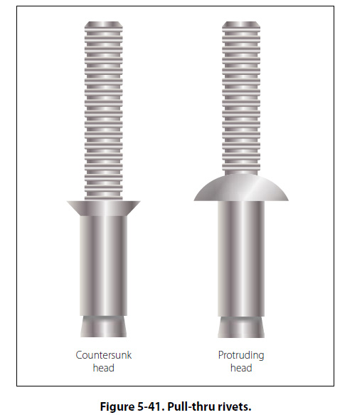
Pull-Thru Rivets The pull-thru blind rivets are manufactured by several companies; the same general basic information about their fabrication, composition, uses, selection, installation, inspection, and removal procedures apply to all of them. Pull-thru rivets are fabricated in two parts: a rivet head with a hollow shank or sleeve and a stem that extends through the hollow shank. Figure 5-41 illustrates a protruding head and a countersunk head pull-thru rivet.
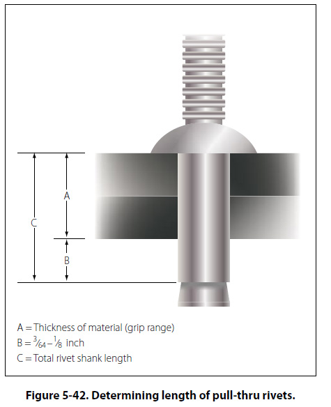
Several events, in their proper sequence, occur when a pulling force is applied to the stem of the rivet: (1) The stem is pulled through the rivet shank; (2) the mandrel portion of the stem forces the shank to expand forming the blind head and filling the hole. Pull-thru rivets are fabricated in two common head styles: (1) protruding head similar to the MS20470 or universal head, and (2) a 100° countersunk head. Other head styles are available from some manufacturers. Pull-thru rivets are fabricated from several materials. Following are the most commonly used: 2117-T4 aluminum alloy, 5056 aluminum alloy, Monel. Pull-thru rivets are designed so that installation requires only one person; it is not necessary to have the work accessible from both sides. Factors to consider in the selection of the correct rivet for installation are: (1) installation location (2) composition of the material being riveted (3) thickness of the material being riveted, (4) strength desired. The thickness of the material being riveted determines the overall length of the shank of the rivet. As a general rule, the shank of the rivet should extend beyond the material thickness approximately 3/64 inch to 1/8 inch before the stem is pulled. [Figure 5-42]
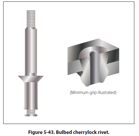
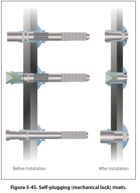
Each company that manufactures pull-thru rivets has a code number to help users obtain correct rivet for the grip range of a particular installation. In addition, MS numbers are used for identification purposes. Numbers are similar to those shown on the preceding pages. Self-Plugging Rivets (Mechanical Lock) Self-plugging (mechanical lock) rivets are similar to self-plugging (friction lock) rivets, except for the manner in which the stem is retained in the rivet sleeve. This type of rivet has a positive mechanical locking collar to resist vibrations that cause the friction lock rivets to loosen and possibly fall out. [Figure 5-45] Also, the mechanical locking type rivet stem breaks off flush with the head and usually does not require further stem trimming when properly installed. Self-plugging (mechanical lock) rivets display all the strength characteristics of solid shank rivets and in most cases can be substituted rivet for rivet. Bulbed Cherrylock Rivets The large blind head of this fastener introduced the word “bulb" to blind rivet terminology. In conjunction with the unique residual preload developed by the high stem break load, its proven fatigue strength makes it the only blind rivet interchangeable structurally with solid rivets. [Figure 5-43]
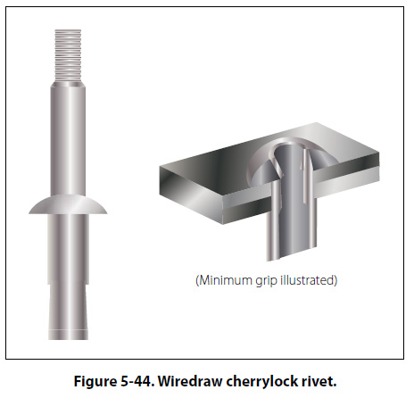
Wiredraw Cherrylock Rivets There is a wide range of sizes, materials, and strength levels from which to select. This fastener is especially suited for sealing applications and joints requiring an excessive amount of sheet takeup. [Figure 5-44]
Huck Mechanical Locked Rivets Self-plugging (mechanical lock) rivets are fabricated in two sections: a head and shank (including a conical recess and locking collar in the head), and a serrated stem that extends through the shank. Unlike the friction lock rivet, the mechanical lock rivet has a locking collar that forms a positive lock for retention of the stem in the shank of the rivet. This collar is seated in position during the installation of the rivet. Material Self-plugging (mechanical lock) rivets are fabricated with sleeves (rivet shanks) of 2017 and 5056 aluminum alloys, Monel, or stainless steel.
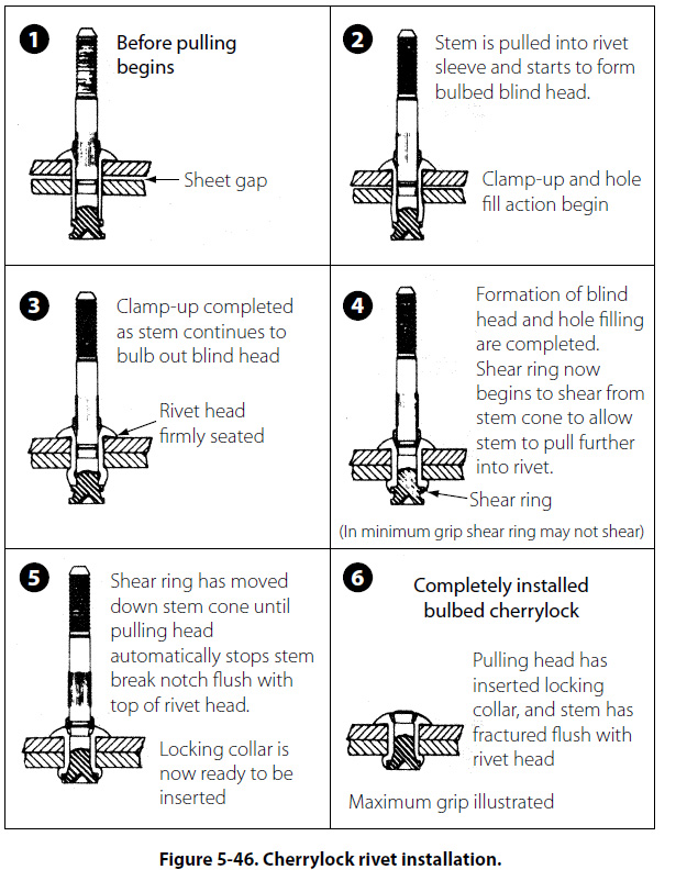
The mechanical lock type of self-plugging rivet can be used in the same applications as the friction lock type of rivet. In addition, because of its greater stem retention characteristic, installation in areas subject to considerable vibration is recommended. The same general requirements must be met in the selection of the mechanical lock rivet as for the friction lock rivet. Composition of the material being joined together determines the composition of the rivet sleeve; for example, 2017 aluminum alloy rivets for most aluminum alloys and 5056 aluminum rivets for magnesium. Figure 5-46 depicts the sequences of a typical mechanically locked blind rivet. The form and function may vary slightly between blind rivet styles and specifics should be obtained from manufacturers.
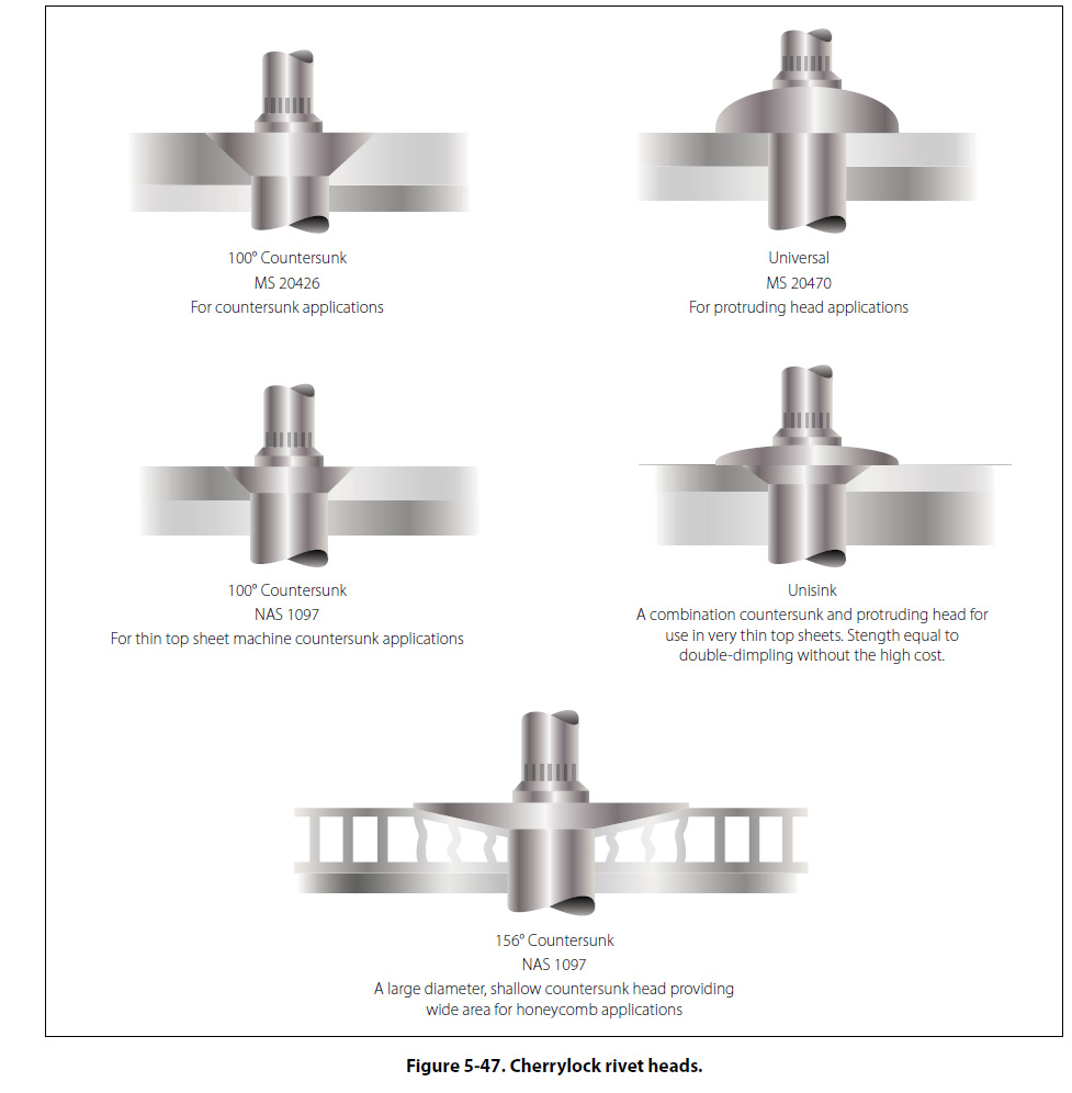
Head Styles Self-plugging mechanical locked blind rivets are available in several head styles depending on the installation requirements. [Figure 5-47]
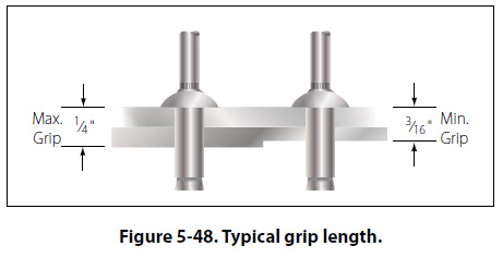
Diameters Shank diameters are measured in 1/32-inch increments and are generally identified by the first dash number: -3 indicates 3/32 inch diameter, -4 indicates 1/8 inch diameter, and so forth. Both nominal and 1/64-inch oversize diameters are available. Grip Length Grip length refers to the maximum total sheet thickness to be riveted and is measured in 1/6 of an inch. This is generally identified by the second dash number. Unless otherwise noted, most blind rivets have their grip lengths (maximum grip) marked on the rivet head and have a total grip range of 1/16 inch. [Figure 5-48]
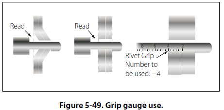
To determine the proper grip rivet to use, measure the material thickness with a grip selection gauge (available from blind rivet manufacturers). The proper use of a grip selector gauge is shown in Figure 5-49.
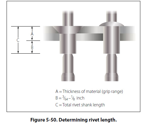
The thickness of the material being riveted determines the overall length of the shank of the rivet. As a general rule, the shank of the rivet should extend beyond the material thickness approximately 3/64 inch to 1/8 inch before the stem is pulled. [Figure 5-50]
|
| ©AvStop Online Magazine Contact Us Return To Books |