![]()
|
|
||
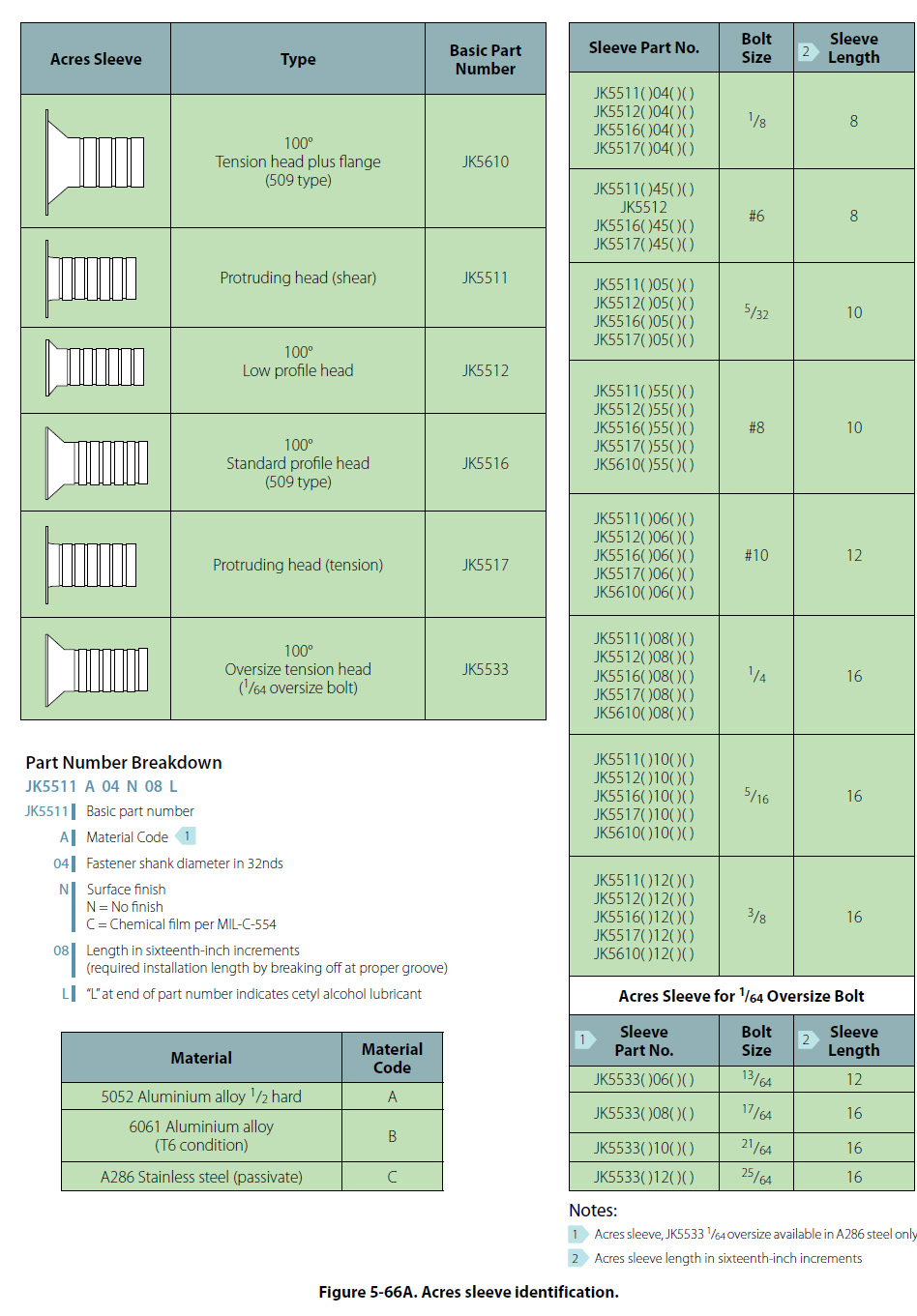
Hole Repair and Hole Repair Hardware Many of the blind fasteners are manufactured in oversized diameters to accommodate slightly enlarged holes resulting from drilling out the original fastener. When using rivets or even bolts, care must be taken to ensure the hole is not elongated or slanted. To reduce the chances of an incorrectly drilled rivet or bolt hole, use a slightly smaller drill bit first, then enlarge to the correct diameter. The last step to prepare the hole for the fastener is to deburr the hole using either a very large drill bit or a special deburring tool. This practice also works well when drilling out a previously attached fastener. If the drill bit does not exactly find the center of the rivet or bolt or screw, the hole can easily be elongated, but when using a smaller drill bit, drill the head only off the fastener, then the ring and stem that is left can be pushed out with a pin punch of the appropriate diameter. If an incorrectly drilled hole is found, the options are to redrill the hole to the next larger diameter for an acceptable fastener or repair the hole using an Acres fastener sleeve. Repair of Damaged Holes with Acres Fastener Sleeves Acres fastener sleeves are thin-wall tubular elements with a flared end. The sleeves are installed in holes to accept standard bolts and rivet-type fasteners. The existing fastener holes are drilled 1/64 inch oversize for installation of the sleeves. The sleeves are manufactured in 1-inch increments. Along their length, grooves provide a place to break or cut off excess length to match fastener grip range. The grooves also provide a place to hold adhesive or sealing agents when bonding the sleeve into the hole. Advantages and Limitations The sleeves are used in holes which must be drilled 1/64 inch oversize to clean up corrosion or other damage. The oversize hole with the sleeve installed allows the use of the original diameter fastener in the repaired hole. The sleeves can be used in areas of high galvanic corrosion where the corrosion must be confined to a readily replaceable part. Oversizing of holes reduces the net cross-sectional area of a part and should not be done unless absolutely required. Consult the manufacturer of the aircraft, aircraft engine or aircraft component prior to repair of damaged holes with Acres sleeves. Identification The sleeve is identified by a standard code number [Figure 5-66A] which represents the type and style of sleeve, a material code, the fastener shank diameter, surface finish code letter and grip tang for the sleeve.
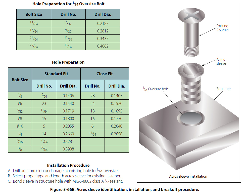
The type and material of the sleeve is represented by the basic code number. The first dash number represents the diameter of the sleeve for the fastener installed and the second dash represents the grip length of the sleeve. The required length of the sleeve is determined on installation and the excess is broken off of the sleeve. A JK5512A-05N-10 is a 100° low profile head sleeve of aluminum alloy. The diameter is for a 5/32-inch fastener with no surface finish and is 5/8 inch in length. Hole Preparation Refer to Figure 5-66B for drill number for standard or close fit holes. Inspect hole after drilling to assure all corrosion is removed before installing the sleeve. The hole must also be the correct shape and free from burrs. The countersink must be enlarged to receive the flare of the sleeve so the sleeve is flush with the surrounding surface. Installation After selecting the correct type and diameter sleeve, use the 6501 sleeve breakoff tool for final installation length. Refer to Figure 5-66B for the sleeve breakoff procedure.
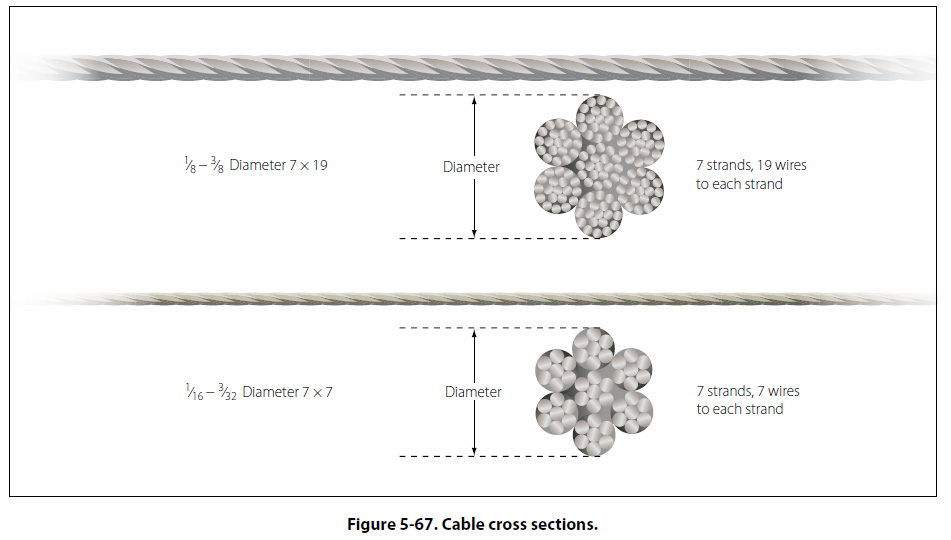
The sleeve may be installed with or without being bonded in the hole. When bonding the sleeve in a hole, use MIL-S-8802A1/2 sealant. Reinstall original size fastener and torque as required. Sleeve Removal Sleeves not bonded in the hole may be removed by either driving them out with a drift pin of the same diameter as the outside diameter of the sleeve or they may be deformed and removed with a pointed tool. Bonded sleeves may be removed by this method, but care should be used not to damage the structure hole. If this method cannot be used, drill the sleeves out with a drill 0.004 to 0.008 inch smaller than the installation drill size. The remaining portion of the sleeve after drilling can be removed using a pointed tool and applying an adhesive solvent to the sealant. Control Cables and Terminals Cables are the most widely used linkage in primary flight control systems. Cable-type linkage is also used in engine controls, emergency extension systems for the landing gear, and various other systems throughout the aircraft. Cable-type linkage has several advantages over the other types. It is strong and light weight, and its flexibility makes it easy to route through the aircraft. An aircraft cable has a high mechanical efficiency and can be set up without backlash, which is very important for precise control. Cable linkage also has some disadvantages. Tension must be adjusted frequently due to stretching and temperature changes. Aircraft control cables are fabricated from carbon steel or stainless steel. Cable Construction The basic component of a cable is a wire. The diameter of the wire determines the total diameter of the cable. A number of wires are preformed into a helical or spiral shape and then formed into a strand. These preformed strands are laid around a straight center strand to form a cable. Cable designations are based on the number of strands and the number of wires in each strand. The most common aircraft cables are the 7 × 7 and 7 × 19. The 7 × 7 cable consists of seven strands of seven wires each. Six of these strands are laid around the center strand. [Figure 5-67] This is a cable of medium flexibility and is used for trim tab controls, engine controls, and indicator controls.
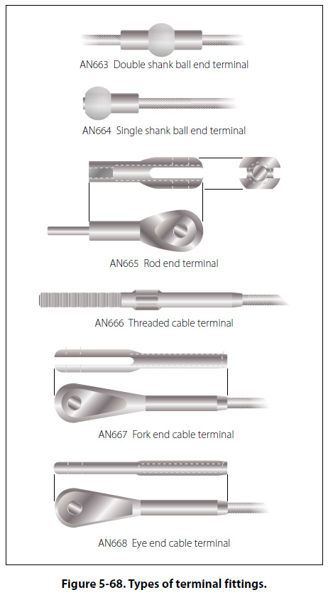
The 7 × 19 cable is made up of seven strands of 19 wires each. Six of these strands are laid around the center strand. [Figure 5-67] This cable is extra flexible and is used in primary control systems and in other places where operation over pulleys is frequent. Aircraft control cables vary in diameter, ranging from 1/16 to 3/8 inch. The diameter is measured as shown in Figure 5-67. Cable Fittings Cables may be equipped with several different types of fittings, such as terminals, thimbles, bushings, and shackles. Terminal fittings are generally of the swaged type. They are available in the threaded end, fork end, eye end, single shank ball end, and double shank ball end. The threaded end, fork end, and eye end terminals are used to connect the cable to a turnbuckle, bellcrank, or other linkage in the system. The ball end terminals are used for attaching cables to quadrants and special connections where space is limited. Figure 5-68 illustrates the various types of terminal fittings.
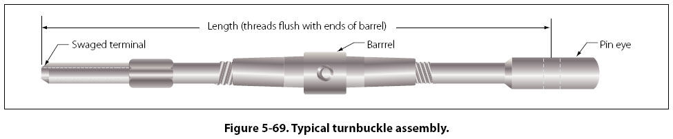
The thimble, bushing, and shackle fittings may be used in place of some types of terminal fittings when facilities and supplies are limited and immediate replacement of the cable is necessary. Turnbuckles A turnbuckle assembly is a mechanical screw device consisting of two threaded terminals and a threaded barrel. [Figure 5-69]
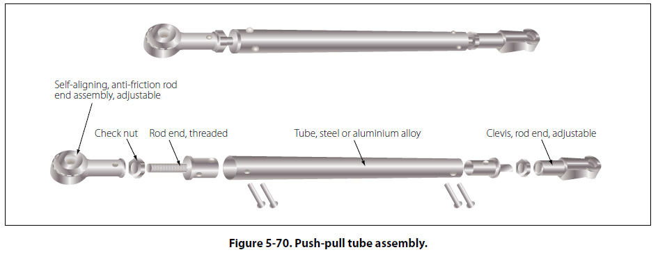
Turnbuckles are fitted in the cable assembly for the purpose of making minor adjustments in cable length and for adjusting cable tension. One of the terminals has right-hand threads and the other has left-hand threads. The barrel has matching right- and left-hand internal threads. The end of the barrel with the left-hand threads can usually be identified by a groove or knurl around that end of the barrel. When installing a turnbuckle in a control system, it is necessary to screw both of the terminals an equal number of turns into the barrel. It is also essential that all turnbuckle terminals be screwed into the barrel until not more than three threads are exposed on either side of the turnbuckle barrel. After a turnbuckle is properly adjusted, it must be safetied. The methods of safetying turnbuckles are discussed later in this chapter. Push-Pull Tube Linkage Push-pull tubes are used as linkage in various types of mechanically operated systems. This type linkage eliminates the problem of varying tension and permits the transfer of either compression or tension stress through a single tube. A push-pull tube assembly consists of a hollow aluminum alloy or steel tube with an adjustable end fitting and a checknut at either end.
[Figure 5-70] The checknuts secure the end fittings after the tube assembly has been adjusted to its correct length. Push-pull tubes are generally made in short lengths to prevent vibration and bending under compression loads. |
| ©AvStop Online Magazine Contact Us Return To Books |