![]()
|
|
||
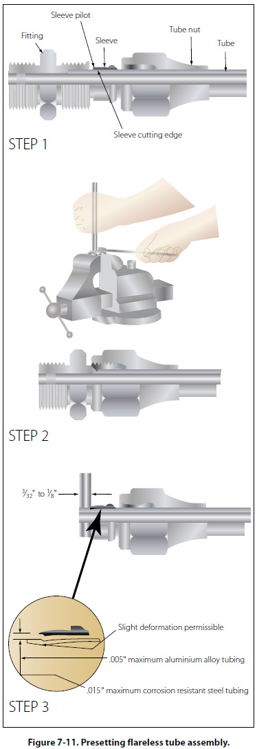
Fittings Rigid tubing may be joined to either an end item (such as a brake cylinder), another section of either rigid tubing, or to a flexible hose (such as a drain line). In the case of connection to an end item or another tube, fittings are required, which may or may not necessitate flaring of the tube. In the case of attachment to a hose, it may be necessary to bead the rigid tube so that a clamp can be used to hold the hose onto the tube. Flareless Fittings Although the use of flareless tube fittings eliminates all tube flaring, another operation, referred to as presetting, is necessary prior to installation of a new flareless tube assembly. Flareless tube assemblies should be preset with the proper size presetting tool or operation. Figure 7-11 (steps 1, 2, and 3) illustrates the presetting operation, which is performed as follows:
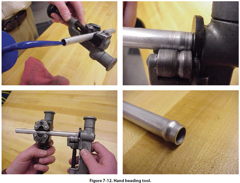
Cut the tube to the correct length, with the ends perfectly square. Deburr the inside and outside of the tube. Slip the nut, then the sleeve, over the tube (step 1), lubricate the threads of the fitting and nut with hydraulic fluid. Place the fitting in a vise (step 2), and hold the tubing firmly and squarely on the seat in the fitting. (The tube must bottom firmly in the fitting.) Tighten the nut until the cutting edge of the sleeve grips the tube. To determine this point, slowly turn the tube back and forth while tightening the nut. When the tube no longer turns, the nut is ready for tightening. Final tightening depends upon the tubing (step 3). For aluminum alloy tubing up to and including 1/2" outside diameter, tighten the nut from 1 to 11/6 turns. For steel tubing and aluminum alloy tubing over 1/2" outside diameter, tighten from 11/6 to 11/2 turns. After presetting the sleeve, disconnect the tubing from the fitting and check the following points: The tube should extend 3/32" to 1/8" beyond the sleeve pilot; otherwise, blowoff may occur. The sleeve pilot should contact the tube or have a maximum clearance of 0.005" for aluminum alloy tubing or 0.015" for steel tubing. A slight collapse of the tube at the sleeve cut is permissible. No movement of the sleeve pilot, except rotation, is permissible. Beading Tubing may be beaded with a hand beading tool, with machine beading rolls, or with grip dies. The method to be used depends on the diameter and wall thickness of the tube and the material from which it was made. The hand beading tool is used with tubing having 1/4" to 1" outside diameter. The bead is formed by using the beader frame with the proper rollers attached. The inside and outside of the tube is lubricated with light oil to reduce the friction between the rollers during beading. The sizes, marked in sixteenths of an inch on the rollers, are for the outside diameter of the tubing that can be beaded with the rollers. [Figure 7-12]
Separate rollers are required for the inside of each tubing size, and care must be taken to use the correct parts when beading. The hand beading tool works somewhat like the tube cutter in that the roller is screwed down intermittently while rotating the beading tool around the tubing. In addition, a small vise (tube holder) is furnished with the kit. Other methods and types of beading tools and machines are available, but the hand beading tool is used most often. As a rule, beading machines are limited to use with large diameter tubing, over 115/16", unless special rollers are supplied. The grip-die method of beading is confined to small tubing. |
| ©AvStop Online Magazine Contact Us Return To Books |