In some ac meters, selenium or vacuum tube rectifiers are used in place of the copper-oxide rectifier. The principle of operation, however, is the same in all meters employing rectifiers.
A dc meter, such as an ammeter, connected in an ac circuit will indicate zero, because the moving ammeter coil that carries the current to be measured is located in a permanent magnet field. Since the field of a permanent magnet remains constant and in the same direction at all times, the moving coil follows the polarity of the current. The coil attempts to move in one direction during half of the ac cycle and in the reverse direction during the other half when the current reverses.
The current reverses direction too rapidly for the coil to follow, causing the coil to assume an average position. Since the current is equal and opposite during each half of the ac cycle, the direct current meter indicates zero, which is the average value. Thus, a meter with a permanent magnet cannot be used to measure alternating voltage and current. However, the permanent magnet D'Arsonval meter may be used to measure alternating current or voltage if the current that passes through the meter is first rectified - that is, changed from alternating current to direct current.
Rectifier AC Meters
Copper-oxide rectifiers are generally used with D'Arsonval dc meter movements to measure alternating currents and voltages; however, there are many types of rectifiers which may be used, some of which are included in the discussion of alternator systems.
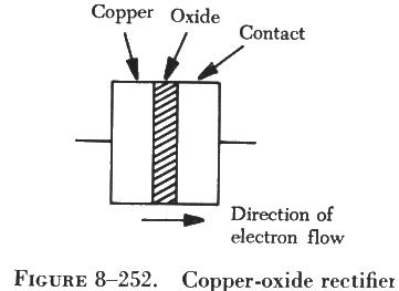
| A copper-oxide rectifier allows current to flow through
a meter in only one direction. As shown in figure 8-252, the copper-oxide
rectifier consists of copper-oxide disks separated alternately by copper
disks and fastened together as a single unit. Current flows more readily
from copper to copper oxide than from copper oxide to copper. When ac is
applied, therefore, current flows in only one direction, yielding a pulsating
dc output as shown by the output wave shapes in figure
8-253. This current can then be measured as it flows through the meter
movement.
In some ac meters, selenium or vacuum tube rectifiers are used in place of the copper-oxide rectifier. The principle of operation, however, is the same in all meters employing rectifiers. |
|
Electrodynamometer Meter Movement
The electrodynamometer meter can be used to measure alternating or direct voltage and current. It operates on the same principles as the permanent magnet moving coil meter, except that the permanent magnet is replaced by an air core electromagnet. The field of the electrodynamometer meter is developed by the same current that flows through the moving coil (see figure 8-254).
In the electrodynamometer meter, two stationary field coils are connected in series with the movable coil. The movable coil is attached to the central shaft and rotates inside the two stationary field coils. The spiral springs provide the restraining force for the meter and also a means of introducing current to the movable coil.
When current flows through field coils A and B and movable coil C, coil C rotates in opposition to the springs and places itself parallel to the field coils. The more current flowing through the coils, the more the moving coil overcomes the opposition of the springs and the farther the pointer moves across the scale. If the scale is properly calibrated and the proper shunts or multipliers are used, the dynamometer movement will indicate current or voltage.
Although electrodynamometer meters are very accurate, they do not have the sensitivity of D'Arsonval meters and, for this reason, are not widely used outside the laboratory.
Electrodynamometer Ammeter
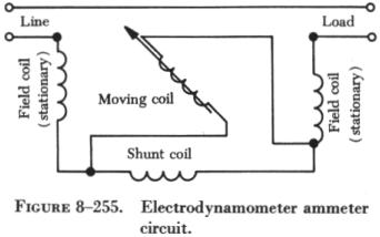
| In the electrodynamometer ammeter, low resistance coils produce only a small voltage drop in the circuit measured. An inductive shunt is connected in series with the field coils. This shunt, similar to the resistor shunt used in dc ammeters, permits only part of the current being measured to flow through the coils. As in the dc ammeter, most of the current in the circuit flows through the shunt; but the scale is calibrated accordingly, and the meter reads the total current. An ac ammeter, like a dc ammeter, is connected in series with the circuit in which current is measured. Effective values are indicated by the meter. A schematic diagram of an electrodynamometer ammeter circuit is shown in figure 8-255. |
 |
Electrodynamometer Voltmeter
In the electrodynamometer voltmeter, field coils are wound with many turns of small wire. Approximately 0.01 ampere of current flow through both coils is required to operate the meter. Resistors of a noninductive material, connected in series with the coils, provide for different voltage ranges. Voltmeters are connected in parallel across the unit in which voltage is to be measured. The values of voltages indicated are effective values. A schematic diagram of an electrodynamometer voltmeter is shown in figure 8-256.
Moving Iron Vane Meter
|
The moving iron vane meter is another basic type of meter. It can be used to measure either ac or dc. Unlike the D'Arsonval meter, which employs permanent magnets, it depends on induced magnetism for its operation. It utilizes the principle of repulsion between two concentric iron vanes, one fixed and one movable, placed inside a solenoid, as shown in figure 8-257. A pointer is attached to the movable vane. When current flows through the coil, the two iron vanes become magnetized with north poles at their upper ends and south poles at their lower ends for one direction of current through the coil. Because like poles repel, the unbalanced component of force, tangent to the movable element, causes it to turn against the force exerted by the springs. |
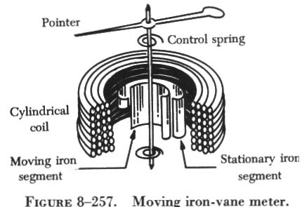 |
The movable vane is rectangular in shape and the fixed vane is tapered. This design permits the use of a relatively uniform scale.
When no current flows through the coil, the movable vane is positioned so that it is opposite the larger portion of the tapered fixed vane, and the scale reading is zero. The amount of magnetization of the vanes depends on the strength of the field, which, in turn, depends on the amount of current flowing through the coil.
The force of repulsion is greater opposite the larger end of the fixed vane than it is nearer the smaller end. Therefore, the movable vane moves toward the smaller end through an angle that is proportional to the magnitude of the coil current. The movement ceases when the force of repulsion is balanced by the restraining force of the spring.
Because the repulsion is always in the same direction (toward the smaller end of the fixed vane), regardless of the direction of current flow through the coil, the moving iron vane instrument operates on either dc or ac circuits.
Mechanical damping in this type of instrument can be obtained by the use of an aluminum vane attached to the shaft so that, as the shaft moves, the vane moves in a restricted air space.
When the moving iron vane meter is designed to be used as an ammeter, the coil is wound with relatively few turns of large wire in order to carry the rated current.
When the moving iron vane meter is designed to be used as a voltmeter, the solenoid is wound with many turns of small wire. Portable voltmeters are made with selfcontained series resistance for ranges up to 750 volts. Higher ranges are obtained by the use of additional external multipliers.
The moving iron vane instrument may be used to measure direct current but has an error due to residual magnetism in the vanes. The error may be minimized by reversing the meter connections and averaging the readings. When used on ac circuits the instrument has an accuracy of 0.5 percent. Because of its simplicity, its relatively low cost, and the fact that no current is conducted to the moving element, this type of movement is used extensively to measure current and voltage in ac power circuits. However, because the reluctance of the magnetic circuit is high, the moving iron vane meter requires much more power to produce full scale deflection than is required by a D'Arsonval meter of the same range. Therefore, the moving iron vane meter is seldom used in high resistance low power circuits.
Inclined Coil Iron Vane Meter
The principle of the moving iron vane mechanism is applied to the inclined coil type of meter, which can be used to measure both ac and dc. The inclined coil, iron vane meter has a coil mounted at an angle to the shaft. Attached obliquely to the shaft, and located inside the coil, are two soft iron vanes. When no current flows through the coil, a control spring holds the pointer at zero, and the iron vanes lie in planes parallel to the plane of the coil. When current flows through the coil, the vanes tend to line up with magnetic lines passing through the center of the coil at right angles to the plane of the coil. Thus, the vanes rotate against the spring action to move the pointer over the scale.
The iron vanes tend to line up with the magnetic lines regardless of the direction of current flow through the coil. Therefore, the inclined coil, iron vane meter can be used to measure either alternating current or direct current. The aluminum disk and the drag magnets provide electromagnetic damping.
Like the moving iron vane meter, the inclined coil type requires a relatively large amount of current for full scale deflection and is seldom used in high resistance low power circuits.
As in the moving iron vane instruments, the inclined coil instrument is wound with few turns of relatively large wire when used as an ammeter and with many turns of small wire when used as a voltmeter.
Thermocouple Meter
If the ends of two dissimilar metals are welded together and this junction is heated, a dc voltage is developed across the two open ends. The voltage developed depends on the material of which the wires are made and on the difference in temperature between the heated junction and the open ends.
In one type of instrument, the junction is heated electrically by the flow of current through a heater element. It does not matter whether the current is alternating or direct because the heating effect is independent of current direction. The maximum current that can be measured depends on the current rating of the heater, the heat that the thermocouple can stand without being damaged, and on the current rating of the meter used with the thermocouple. Voltage can also be measured if a suitable resistor is placed in series with the heater. In meter applications, a D'Arsonval meter is used with a resistance wire heater, as shown in figure 8-258.
As current flows through the resistance wire, the heat developed is
transferred to the contact point and develops an e.m.f. which causes current
to flow through the meter. The coil rotates and causes the pointer to move
over a calibrated scale. The amount of coil movement is dependent on the
amount of heat, which varies as the square of the current. Thermocouple
meters are used extensively in ac measurements.
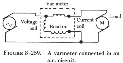
| Varmeters
Multiplying the volts by the amperes in an ac circuit gives the apparent power: the combination of the true power which does the work and the reactive power which does no work and is returned to the line. Reactive power is measured in units of vars (volt-amperes reactive) or kilovars (kilovolt-amperes reactive, abbreviated KVAR). When properly connected, wattmeters measure the reactive power. As such, they are called varmeters. The illustration in figure 8-259 shows a varmeter connected in an ac circuit. |
 |
Wattmeter
Electric power is measured by means of a wattmeter. Because electric power is the product of current and voltage, a wattmeter must have two elements, one for current and the other for voltage, as indicated in figure 8-260. For this reason, wattmeters are usually of the electrodynamometer type.
The movable coil with a series resistance forms the voltage element, and the stationary coils constitute the current element. The strength of the field around the potential coil depends on the amount of current that flows through it. The current, in turn, depends on the load voltage applied across the coil and the high resistance in series with it. The strength of the field around the current coils depends on the amount of current flowing through the load. Thus, the meter deflection is proportional to the product of the voltage across the potential coil and the current through the current coils. The effect is almost the same (if the scale is properly calibrated) as if the voltage applied across the load and the current through the load were multiplied together.
If the current in the line is reversed, the direction of current in
both coils and the potential coil is reversed, the net result is that the
pointer continues to read up scale. Therefore, this type of wattmeter can
be used to measure either ac or dc power.