
Alternating current has largely replaced direct current in commercial power systems for a number of reasons. It can be transmitted over long distances more readily and more economically than direct current, since ac voltages can be increased or decreased by means of transformers.
Because more and more units are being operated electrically in airplanes, the power requirements are such that a number of advantages can be realized by using ac. Space and weight can be saved, since ac devices, especially motors, are smaller and simpler than dc devices. In most ac motors no brushes are required, and commutation trouble at high altitude is eliminated. Circuit breakers will operate satisfactorily under load at high altitudes in an ac system, whereas arcing is so excessive on dc systems that circuit breakers must be replaced frequently. Finally, most airplanes using a 24 volt dc system have special equipment which requires a certain amount of 400 cycle ac current.
AC and DC Compared
Many of the principles, characteristics, and effects of alternating current are similar to those of direct current. Similarly, there are a number of differences which are explained later. Direct current flows constantly in only one direction with a constant polarity. It changes magnitude only when the circuit is opened or closed, as shown in the dc wave form in figure 8-160. Alternating current changes direction at regular intervals, increases in value at a definite rate from zero to a maximum positive strength, and decreases back to zero; then it flows in the opposite direction, similarly increasing to a maximum negative value, and again decreasing to zero. DC and ac wave forms are compared in figure 8-160.
Since alternating current constantly changes direction and intensity, two effects take place in ac circuits that do not occur in dc circuits. They are inductive reactance and capacitive reactance. Both are discussed later in this chapter.
Generator Principles
After the discovery that an electric current flowing through a conductor creates a magnetic field around the conductor, there was considerable scientific speculation about whether a magnetic field could create a current flow in a conductor. In 1831, the English scientist, Michael Faraday, demonstrated this could be accomplished. This discovery is the basis for the operation of the generator, which signalled the beginning of the electrical age.
To show how an electric current can be created by a magnetic field, a demonstration similar to that illustrated in figure 8-161 can be used. Several turns of a conductor are wrapped around a cylindrical form, and the ends of the conductor are connected together to form a complete circuit which includes a galvanometer. If a simple bar magnet is plunged into the cylinder, the galvanometer can be observed to deflect in one direction from its zero (center) position (A of figure 8-161).
When the magnet is at rest inside the cylinder, the galvanometer shows a reading of zero, indicating that no current is flowing (B of figure 8-161).
In C of figure 8-161, the galvanometer indicates a current flow in the opposite direction when the magnet is pulled from the cylinder.
The same results may be obtained by holding the magnet stationary and
moving the cylinder over the magnet, indicating that a current flows when
there is relative motion between the wire coil and the magnetic field.
These results obey a law first stated by the German scientist, Heinrich
Lenz. Lenz's law states that the induced current caused by the relative
motion of a conductor and a magnetic field always flows in such a direction
that its magnetic field opposes the motion.
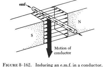 |
When a conductor is moved through a magnetic field, as shown in figure 8-162, an electromotive force (e.m.f.) is induced in the conductor. The direction (polarity) of the induced e.m.f. is determined by the magnetic lines of force and the direction the conductor is moved through the magnetic field. The generator left-hand rule (not to be confused with the left-hand rules used with a coil) can be used to determine the direction of the induced e.m.f., as shown in figure 8-163. The first finger of the left hand is pointed in the direction of the magnetic lines of force (north to south), the thumb is pointed in the direction of movement of the conductor through the magnetic field, and the second finger points in the direction of the induced e.m.f. When two of these three factors are known, the third may be determined by the use of this rule. |
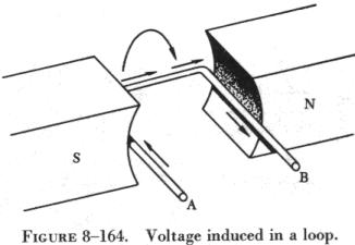
| When a loop conductor is rotated in a magnetic field (see
figure 8-164), a voltage is induced in each side of the loop. The two sides
cut the magnetic field in opposite directions, and although the current
flow is continuous, it moves in opposite directions with respect to the
two sides of the loop. If sides A and B and the loop are rotated half a
turn and the sides of the conductor have exchanged positions, the induced
e.m.f. in each wire reverses its direction, since the wire formerly cutting
the lines of force in an upward direction is now moving downward.
The value of an induced e.m.f. depends on three factors: (1) The number of wires moving through the magnetic field.
|
 |
Generators of Alternating Current
Generators used to produce an alternating current are called ac generators or alternators.
The simple generator shown in figure 8-165 constitutes one method of generating an alternating voltage. It consists of a rotating loop, marked A and B, placed between two magnetic poles, N and S. The ends of the loop are connected to two metal slip rings (collector rings), C1 and C2. Current is taken from the collector rings by brushes. If the loop is considered as separate wires A and B, and the left-hand rule for generators (not to be confused with the left-hand rule for coils) is applied, then it can be observed that as wire A moves up across the field, a voltage is induced which causes the current to flow inward. As wire B moves down across the field, a voltage is induced which causes the current to flow outward. When the wires are formed into a loop, the voltages induced in the two sides of the loop are combined. Therefore, for explanatory purposes, the action of either conductor, A or B, while rotating in the magnetic field is similar to the action of the loop.
Figure 8-166 illustrates the generation of alternating current with a simple loop conductor rotating in a magnetic field. As it is rotated in a counterclockwise direction, varying values of voltages are induced in it. At position 1, conductor A moves parallel to the lines of force. Since it cuts no lines of force, the induced voltage is zero. As the conductor advances from position 1 to position 2, the voltage induced gradually increases. At 2, the conductor moves perpendicular to the flux and cuts a maximum number of lines of force; therefore, a maximum voltage is induced. As the conductor moves beyond 2, it cuts a decreasing amount of flux at each instant, and the induced voltage decreases. At 3, the conductor has made one half of a revolution and again moves parallel to the lines of force, and no voltage is induced in the conductor.
As the A conductor passes position 3, the direction of induced voltage reverses since the A conductor now moves downward, cutting flux in the opposite direction. As the A conductor moves across the south pole, the induced voltage gradually increases in a negative direction, until at position 4 the conductor again moves perpendicular to the flux and generates a maximum negative voltage. From position 4 to 5, the induced voltage gradually decreases until the voltage is zero, and the conductor and wave are ready to start another cycle.
The curve shown at position 5 is called a sine wave. It represents the polarity and the magnitude of the instantaneous values of the voltages generated. The horizontal base line is divided into degrees, or time, and the vertical distance above or below the base line represents the value of voltage at each particular point in the rotation of the loop.
Cycle and Frequency
Whenever a voltage or current passes through a series of changes, returns to the starting point, and then again starts the same series of changes, the series is called a cycle. The cycle is represented by the symbol of a wavy line in a circle. In the cycle of voltage shown in figure 8-167, the voltage increases from zero to a maximum positive value, decreases to zero; then increases to a maximum negative value, and again decreases to zero. At this point it is ready to go through the same series of changes. There are two alternations in a complete cycle, the positive alternation and the negative. Each is half a cycle.
The number of times each cycle occurs in a period of time is called the frequency. The frequency of an electric current or voltage indicates the number of times a cycle recurs in 1 second.
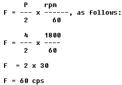
In a generator, the voltage and current pass through a complete cycle of values each time a coil or conductor passes under a north and south pole of the magnet. The number of cycles for each revolution of the coil or conductor is equal to the number of pairs of poles. The frequency, then, is equal to the number of cycles in one revolution multiplied by the number of revolutions per second. Expressed in equation form,
![]()
where P/2 is the number of pairs of poles, and rpm/60 the number of revolutions per second. If in a 2 pole generator, the conductor is turning at 3,600 rpm, the revolutions per second are
![]()
Since there are 2 poles, P/2 is 1, and the frequency is 60 cps. In a 4 pole generator with an armature speed of 1,800 rpm, substitute in the equation,
| In addition to frequency and cycle characteristics, alternating
voltage and current also have a relationship called "phase." In a circuit
that is fed (supplied) by one alternator, there must be a certain phase
relationship between voltage and current if the circuit is to function
efficiently. In a system fed by two or more alternators, not only must
there be a certain phase relationship between voltage and current of one
alternator, but there must be a phase relationship between the individual
voltages and the individual currents. Also, two separate circuits can be
compared by comparing the phase characteristics of one to the phase characteristics
of the other.
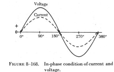
When two or more sine waves pass through 0° and 180° at the same time and reach their peaks at the same time, an in phase condition exists, as shown in figure 8-168. The peak values (magnitudes) do not have to be the same for the in phase condition to exist. |
 |
When the sine waves pass through 0° and 180° at different times and reach their peaks at different times, an out of phase condition exists, as shown in figure 8-169. The amount that the two sine waves are out of phase is indicated by the number of electrical degrees between corresponding peaks on the sine waves. In figure 8-169, the current and voltage are 30° out of phase.
Values of Alternating Current
| There are three values of alternating current which should
be considered. They are instantaneous, maximum, and effective. An instantaneous
value of voltage or current is the induced voltage or current flowing at
any instant. The sine wave is a series of these values. The instantaneous
value of the voltage varies from zero at 0° to maximum at 90°,
back to zero at 180°, to maximum in the opposite direction at 270°,
and to zero again at 360°. Any point on the sine wave is considered
the instantaneous value of voltage.
The maximum value is the largest instantaneous value. The largest single positive value occurs when the sine wave of voltage is at 90°, and the largest single negative value occurs when it is at 270°. These are called maximum values. Maximum value is 1.41 times the effective value. (See figure 8-170.) |
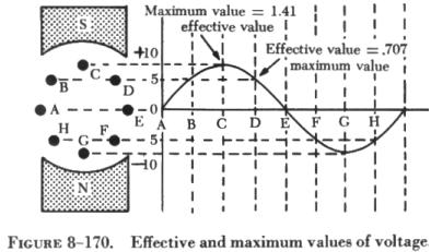 |
The effective value of alternating current is the same as the value of a direct current which can produce an equal heating effect. The effective value is less than the maximum value, being equal to 0.707 times the maximum value. Thus, the 110 volt value given for alternating current supplied to homes is only 0.707 of the maximum voltage of this supply. The maximum voltage is approximately 155 volts (110 x 1.41 = 155 volts maximum).
In the study of alternating current, any values given for current or voltage are assumed to be effective values unless otherwise specified, and in practice, only the effective values of voltage and current are used. Similarly, alternating current voltmeters and ammeters measure the effective value.