
An electrical generator is a machine which converts mechanical energy into electrical energy by electromagnetic induction. A generator which produces alternating current is referred to as an ac generator and, through combination of the words "alternating" and "generator," the word "alternator" has come into widespread use. In some areas, the word "alternator" is applied only to small ac generators. This text treats the two terms synonymously and uses the term "alternator" to distinguish between ac and dc generators.
The major difference between an alternator and a dc generator is the method of connection to the external circuit; that is, the alternator is connected to the external circuit by slip rings, but the dc generator is connected by a commutator.
Types of Alternators
Alternators are classified in several ways in order to distinguish properly the various types. One means of classification is by the type of excitation system used. In alternators used on aircraft, excitation can be affected by one of the following methods:
1. A direct connected, direct current generator. This system consists of a dc generator fixed on the same shaft with the ac generator. A variation of this system is a type of alternator which uses dc from the battery for excitation, after which the alternator is self excited.
2. By transformation and rectification from the ac system. This method depends on residual magnetism for initial ac voltage buildup, after which the field is supplied with rectified voltage from the ac generator.
3. Integrated brushless type. This arrangement has a direct current generator on the same shaft with an alternating current generator. The excitation circuit is completed through silicon rectifiers rather than a commutator and brushes. The rectifiers are mounted on the generator shaft and their output is fed directly to the alternating current generator's main rotating field.
Another method of classification is by the number of phases of output voltage. Alternating current generators may be single phase, two phase, three phase, or even six phase and more. In the electrical systems of aircraft, the three phase alternator is by far the most common.
Still another means of classification is by the type of stator and rotor used. From this standpoint, there are two types of alternators: the revolving armature type and the revolving field type. The revolving armature alternator is similar in construction to the dc generator, in that the armature rotates through a stationary magnetic field. The revolving armature alternator is found only in alternators of low power rating and generally is not used. In the dc generator, the e.m.f. generated in the armature windings is converted into a unidirectional voltage (dc) by means of the commutator. In the revolving armature type of alternator, the generated ac voltage is applied unchanged to the load by means of slip rings and brushes.
The revolving field type of alternator (figure 9-34) has a stationary armature winding (stator) and a rotating field winding (rotor). The advantage of having a stationary armature winding is that the armature can be connected directly to the load without having sliding contacts in the load circuit. A rotating armature would require slip rings and brushes to conduct the load current from the armature to the external circuit. Slip rings have a relatively short service life and arc over is a continual hazard; therefore, high voltage alternators are usually of the stationary armature, rotating field type. The voltage and current supplied to the rotating field are relatively small, and slip rings and brushes for this circuit are adequate. The direct connection to the armature circuit makes possible the use of large cross-section conductors, adequately insulated for high voltage.
Since the rotating field alternator is used almost universally in aircraft systems, this type will be explained in detail, as a single phase, two phase, and three phase alternator.
Single Phase Alternator
Since the e.m.f. induced in the armature of a generator is alternating, the same sort of winding can be used on an alternator as on a dc generator. This type of alternator is known as a single phase alternator, but since the power delivered by a single phase circuit is pulsating, this type of circuit is objectionable in many applications.
A single phase alternator has a stator made up of a number of windings in series, forming a single circuit in which an output voltage is generated. Figure 9-35 illustrates a schematic diagram of a single phase alternator having four poles. The stator has four polar groups evenly spaced around the stator frame. The rotor has four poles, with adjacent poles of opposite polarity. As the rotor revolves, ac voltages are induced in the stator windings. Since one rotor pole is in the same position relative to a stator winding as any other rotor pole, all stator polar groups are cut by equal numbers of magnetic lines of force at any time.
As a result, the voltages induced in all the windings have the same amplitude, or value, at any given instant. The four stator windings are connected to each other so that the ac voltages are in phase, or "series adding." Assume that rotor pole 1, a south pole, induces a voltage in the direction indicated by the arrow in stator winding 1. Since rotor pole 2 is a north pole, it will induce a voltage in the opposite direction in stator coil 2 with respect to that in coil 1.
For the two induced voltages to be in series addition, the two coils are connected as shown in the diagram. Applying the same reasoning, the voltage induced in stator coil 3 (clockwise rotation of the field) is the same direction (counterclockwise) as the voltage induced in coil 1. Similarly, the direction of the voltage induced in winding 4 is opposite to the direction of the voltage induced in coil 1. All four stator coil groups are connected in series so that the voltages induced in each winding add to give a total voltage that is four times the voltage in any one winding.
Two Phase Alternator
Two phase alternators have two or more single phase windings spaced symmetrically around the stator. In a two phase alternator there are two single phase windings spaced physically so that the ac voltage induced in one is 90° out of phase with the voltage induced in the other. The windings are electrically separate from each other. When one winding is being cut by maximum flux, the other is being cut by no flux. This condition establishes a 90° relation between the two phases.
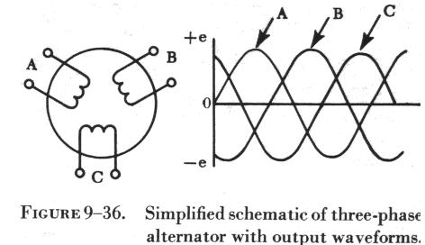
Three Phase Alternator
A three phase, or polyphase circuit,
is used in most aircraft alternators, instead of a single or two phase
alternator. The three phase alternator has three single phase windings
spaced so that the voltage induced in each winding is 120° out of phase
with
| the voltages in the
other two windings. A
schematic diagram of a three phase stator showing all the coils becomes complex and difficult to see what is actually happening. A simplified schematic diagram, showing each of three phases, is illustrated in figure 9-36. The rotor is omitted for simplicity. The waveforms of voltage are shown to the right of the schematic. The three voltages are 120° apart and are similar to the voltages which would be generated by three single phase alternators whose voltages are out of phase by angles of 120°. The three phases are independent of each other. |
 |
Rather than have six leads from the three phase alternator, one of the leads from each phase may be connected to form a common junction. The stator is then called wye or star connected. The common lead may or may not be brought out of the alternator. If it is brought out, it is called the neutral lead. The simplified schematic (A of figure 9-37) shows a wye connected stator with the common lead not brought out. Each load is connected across two phases in series. Thus, RAB is connected across phases A and B in series; RAC is connected across phases A and C in series; and RBC is connected across phases B and C in series. Therefore, the voltage across each load is larger than the voltage across a single phase. The total voltage, or line voltage, across any two phases is the vector sum of the individual phase voltages. For balanced conditions, the line voltage is 1.73 times the phase voltage. Since there is only one path for current in a line wire and the phase to which it is connected, the line current is equal to the phase current.
A three phase stator can also be connected so that the phases are connected end to end as shown in B of figure 9-37. This arrangement is called a delta connection. In a delta connection, the voltages are equal to the phase voltages; the line currents are equal to the vector sum of the phase currents; and the line current is equal to 1.73 times the phase current, when the loads are balanced.
For equal loads (equal kw. output), the delta connection supplies increased line current at a value of line voltage equal to phase voltage, and the wye connection supplies increased line voltage at a value of line current equal to phase current.
Alternator Rectifier Unit
A type of alternator used in the electrical system of many aircraft weighing less than 12,500 pounds is shown in figure 9-38. This type of power source is sometimes called a dc generator, since it is used in dc systems. Although its output is a dc voltage, it is an alternator rectifier unit.
This type of alternator rectifier is a self excited unit but does not contain a permanent magnet. The excitation for starting is obtained from the battery, and immediately after starting, the unit is self exciting. Cooling air for the alternator is conducted into the unit by a blast air tube on the air inlet cover (figure 9-38).
The alternator is directly coupled to the aircraft engine by means of a flexible drive coupling. The dc output voltage may be regulated by a carbon pile voltage regulator. The output of the alternator portion of the unit is three phase alternating current, derived from a three phase, delta connected system incorporating a three phase, full wave bridge rectifier (figure 9-39).
This unit operates in a speed range from 2,100 to 9,000 rpm, with a dc output voltage of 26 - 29 volts and 125 amperes.