BASICCIRCUIT
BASIC CIRCUIT COMPONENTS AND SYMBOLS
| An electrical circuit consists of: (1) A source of electrical
pressure or e.m.f.; (2) resistance in the form of an energy consuming electrical
device; and (3) conductors, usually in the form of copper or aluminum wires,
to provide a path for electron flow from the negative side of the power
source through the resistance and back to the positive side of the power
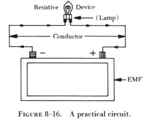
source. Figure 8-16 is a pictorial representation of a practical circuit.
This circuit contains a source of e.m.f. (storage battery), a conductor
to provide a path for the flow of electrons from the negative to the positive
terminal of the battery, and a power dissipating device (lamp) to limit
the current flow. Without some resistance in the circuit the potential
difference between the two terminals would be neutralized very quickly
or the flow of electrons would become so heavy that the conductor would
become overheated and burn. |
|
 |
At the same time that the lamp acts as a current limiting resistance
in the circuit, it is also accomplishing the desired function of creating
light.
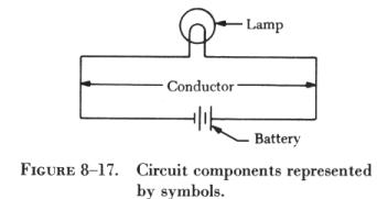
Figure 8-17 is a schematic representation of figure 8-16, in which symbols
rather than pictures are used to represent the circuit components.
All components used in electrical circuits are represented in drawings,
blueprints, and illustrations in schematic form by symbols. The components
commonly used in basic circuits, together with their schematic symbols,
are discussed to provide the necessary background for interpretation of
circuit diagrams. |
Source of Power
The source of power, or applied voltage, for a circuit may be any one
of the common sources of e.m.f , such as a mechanical source (generator),
a chemical source (battery), a photoelectric source (light), or a thermal
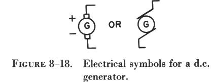
source (heat). Figure 8-18 illustrates two schematic symbols for a generator.
Most electrical components have only one symbol; however, in the case of
the generator and a few others, more than one symbol has been developed
to represent a single electrical component. These symbols are normally
very similar in design. Figure 8-18 illustrates that the two symbols for
a generator are so nearly alike there is little chance for confusion.
Another common source for the voltage applied to a circuit is the battery,
a chemical source of power. Figure 8-19 shows symbols for a single cell
battery and a three cell battery.
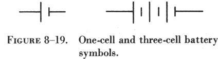
The following statements are true of battery symbols used in schematic
diagrams (refer to figure 8-19):
(1) The shorter vertical line represents the negative terminal.
(2) The longer vertical line is the positive terminal.
(3) The horizontal lines represent the conductors connected to the
terminals.
(4) Each cell of a battery has one negative and one positive terminal.
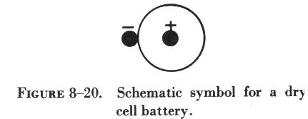
Dry cell batteries, such as those used to operate flashlights, are called
primary cells. The larger storage batteries containing several primary
cells are called secondary cells. The schematic symbol for the primary
cell is shown in figure 8-20. The center rod is the positive terminal of
the cell, and the case of the cell is the negative terminal. When more
than 1.5 volts are required, cells are connected in series. To connect
the cells in series, the negative terminal of each cell is connected to
the positive terminal of the succeeding cell as shown in A of figure
8-21. The voltage is then equal to the sum of the voltages of the individual
cells. Since the same current must flow through each cell in succession,
the current that the battery can supply is equal to the current rating
of a single cell. Thus, a battery composed of cells in series provides
a higher voltage, but not a greater current capacity.
To obtain a greater current flow than one cell is able to supply, the
cells are connected in parallel. The total current available is equal to
the sum of the individual currents from each cell, but the voltage is equal
to the voltage of a single cell. To connect cells in parallel, all positive
terminals are connected together and all negative terminals are connected
together. In A of figure 8-22, a schematic diagram
of cells connected in parallel is shown. B of figure
8-22 illustrates the symbol used to represent this group of cells connected
in parallel. Each cell must have the same voltage; otherwise, a cell with
higher voltage will force current through the lower voltage cells.
Another method of arranging cells is to connect them in series-parallel.
In this method, shown in figure 8-23, two groups
of cells are connected in series, and then these two groups are connected
in parallel. This arrangement provides both a greater voltage and a greater
current output.
Conductor
Another basic requirement of a circuit is the conductor or wire connecting
the various electrical components. This is always represented in schematic
diagrams as a line. Figure 8-24 illustrates two different symbols used
to indicate wires (conductors) that cross but are not connected. While
either of these symbols may be used, the symbol shown in B of figure 8-24
is now found more often, since it is less likely to be misinterpreted.
.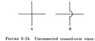
figure 8-25 illustrates the two different
symbols used to represent connected wires. Either of these two symbols
may be used, but it is important that no conflict exists with the symbol
selected to represent unconnected wires. For example, if the symbol for
unconnected wires shown in A of figure 8-24 is selected, the symbol for
connected wires must be that shown in A of figure 8-25.
A circuit component found in all practical circuits is the fuse. This
is a safety or protective device used to prevent damage to the conductors
and circuit components by excessive current flow.

The schematic symbol for a fuse is shown in figure 8-26.
Another symbol found in basic circuit schematics is the symbol for the
switch, shown in figure 8-27. The open switch symbol is shown in A of figure
8-27, and in B of figure 8-27 the closed switch
symbol is shown connected in a circuit. There are many different types
of switches, but these symbols can represent all but the most complex.
Figure 8-28 illustrates the symbol for "ground" or the common reference
point in a circuit. This is the reference point from which most circuit
voltages are measured. This point is normally considered to be at zero
potential.
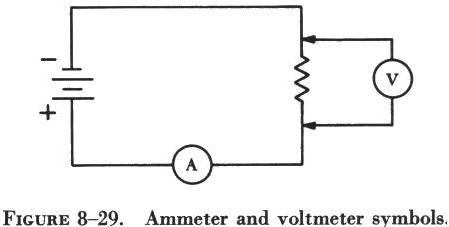 |
Sometimes meters for measuring current flow or voltage are temporarily
connected to the circuit, and in some circuits these meters are permanent
components. In figure 8-29, the symbols for an ammeter and a voltmeter
are used in a simple circuit. It is important that these components be
connected properly. The ammeter, which measures current flow, is always
connected in series with the power source and circuit resistances. The
voltmeter, which measures the voltage across a circuit component, is always
connected across (in parallel with) a circuit component, never in a series
arrangement. |
| Resistors
The last of the basic component requirements of a complete circuit can
be grouped under the single heading of resistance. Resistance in a practical
circuit may take the form of any electrical device, such as a motor or
a lamp, which uses electrical power and produces some useful function.
On the other hand, the resistance of a circuit may be in the form of resistors
inserted in the circuit to limit current flow.
A wide variety of resistors are available. Some have a fixed ohmic value
and others are variable. They are manufactured from special resistance
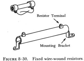
wire, graphite (carbon), or metal film. Wirewound resistors control large
currents, while carbon resistors control relatively small currents. Wirewound
resistors are constructed by winding resistance wire on a porcelain base,
attaching the wire ends to metal terminals, and coating the wire for protection
and heat conduction. (See figure 8-30.) |
|
 |
|
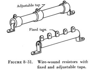
Wirewound resistors are available with fixed taps which can be used
to change the resistance value in increments or steps. They may also be
provided with sliders which can be adjusted to change the resistance to
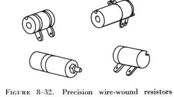
any fraction of the total resistance. (See figure 8-31.) Still another
type is the precision wirewound resistors (figure 8-32) made of manganin
wire. They are used where the resistance value must be very accurate.
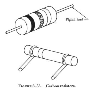
| Carbon resistors are manufactured from a rod of compressed graphite
and binding material, with wire leads, called "pigtail" leads, attached
to each end of the resistor. (See figure 8-33.)
Variable resistors are used to vary the resistance while the equipment
is in operation. Wirewound variable resistors control large currents, and
carbon variable resistors control small currents. Wirewound variable resistors
are constructed by winding resistance wire on a porcelain or bakelite circular
form. A contact arm which can be adjusted to any position on the circular
form by means of a rotating shaft is used to select resistance settings.
(See figure 8-34.)
Carbon variable resistors (see figure 8-35),
used to control small currents, are constructed of a carbon compound deposited
on a fiber disk. A contact on a movable arm varies the resistance as the
arm shaft is turned. |
|
The two symbols used on a schematic or circuit diagram to represent
variable resistors are shown in figure 8-36.
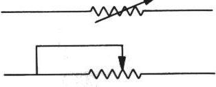
Figure 8-36
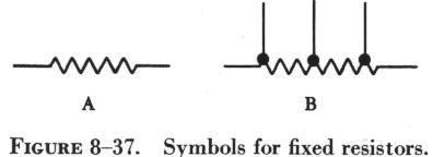
The schematic symbol for a fixed resistor is shown in A of figure 8-37.
A variation of this symbol represents the tapped resistor, which has a
fixed value but is provided with taps from which selected amounts of resistance
can be obtained. (See B of figure 8-37.)
 Resistor Color Code
The resistance value of any resistor can be measured by using an ohmmeter.
But this is seldom necessary. Most wirewound resistors have their resistance
value in ohms printed on the body of the resistor. Many carbon resistors
are similarly marked, but are often mounted in such a manner that it is
difficult or impossible to read the resistance value. Additionally, heat
often discolors the resistor body, making the printed marking illegible,
and many carbon resistors are so small that a printed marking cannot be
used. Thus, a color code marking is used to identify the resistance value
of carbon resistors.
There is only one color code for carbon resistors, but there are two
systems or methods used to paint this color code on resistors. One is the
body-end-dot system, and the other is the end-to-center band system.
In each color code system, three colors are used to indicate the resistance
value in ohms, and a fourth color is sometimes used to indicate the tolerance
of the resistor. By reading the colors in the correct order and by substituting
numbers from the color code, the resistance value of a resistor can be
determined.
It is very difficult to manufacture a resistor to an exact standard
of ohmic values. Fortunately, most circuit requirements are not extremely
critical. For many uses the actual resistance in ohms can be 20 percent
higher or lower than the value marked on the resistor without causing difficulty.
The percentage variation between the marked value and the actual value
of a resistor is known as the "tolerance" of a resistor. A resistor coded
for a 5 percent tolerance will not be more than 5 percent higher or lower
than the value indicated by the color code.
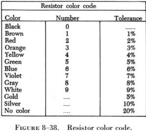
| The resistor color code (see figure 8-38) is made up of
a group of colors, numbers, and tolerance values. Each color is represented
by a number and in most cases by a tolerance value.
When the color code is used with the end-to-center band marking system,
the resistor is normally marked with bands of color at one end of the resistor.
The body or base color of the resistor has nothing to do with the color
code, and in no way indicates a resistance value. To prevent confusion,
this body will never be the same color as any of the bands indicating resistance
value.
When the end-to-center band marking system is used, the resistor will
be marked by either three or four bands. The first color band (nearest
the end of the resistor) will indicate the first digit in the numerical
resistance value. This band will never be gold or silver in color. |
|
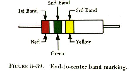
The second color band (refer to figure 8-39) will always indicate the
second digit of ohmic value. It will never be gold or silver in color.
The third color band indicates the number of zeros to be added to the two
digits derived from the first and second bands, except in the following
two cases:
(1) If the third band is gold in color, the first two digits must be
multiplied by 10 percent.
(2) If the third band is silver in color, the first two digits must
be multiplied by 1 percent.
If there is a fourth color band, it is used as a multiplier for percentage
of tolerance, as indicated in the color code chart in figure 8-38. If there
is no fourth band, the tolerance is understood to be 20 percent.
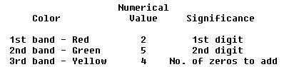
Figure 8-39 illustrates the rules for reading the resistance value of
a resistor marked with the end-to-center band system. This resistor is
marked with three bands of color, which must be read from the end toward
the center.
These are the values that should be obtained:
There is no fourth color band, so the tolerance is understood to be
20 percent. 20 percent of 250,000 = 50,000.
Since the 20 percent tolerance is plus or minus,
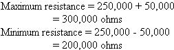
Figure 8-40 contains a resistor with another set of colors. This resistor
code should be read as follows:
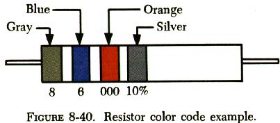
The resistance of this resistor is 86,000 ± 10 percent ohms.
The maximum resistance is 94,600 ohms and the minimum resistance is 77,400
ohms.
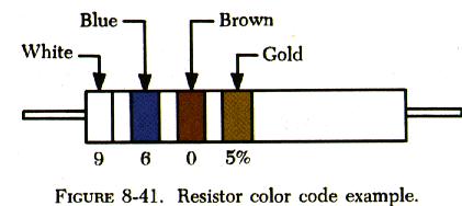
As another example, the resistance of the resistor in figure 8-41 is
960 ± 5 percent ohms. The maximum resistance is 1,008 ohms, and
the minimum resistance is 912 ohms.
Sometimes circuit considerations dictate that the tolerance must be
smaller than 20 percent. Figure 8-42 shows an example of a resistor with
a 2 percent tolerance. The resistance value of this resistor is 2,500 ±
2 percent ohms. The maximum resistance is 2,550 ohms, and the minimum resistance
is 2,450 ohms.
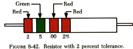
Figure 8-43 contains an example of a resistor with a black third color
band. The color code value of black is zero, and the third band indicates
the number of zeros to be added to the first two digits.
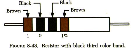
In this case, a zero number of zeros must be added to the first two
digits; therefore, no zeros are added. Thus, the resistance value is 10
± 1 percent ohms. The maximum resistance is 10.1 ohms, and the minimum
resistance is 9.9 ohms. There are two exceptions to the rule stating the
third color band indicates the number of zeros. The first of these exceptions
is illustrated in figure 8-44.
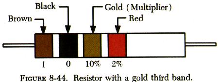
When the third band is gold in color, it indicates that the first two
digits must be multiplied by 10 percent. The value of this resistor is
10 x 0.10 ± 2% = 1 = 0.02 ohms
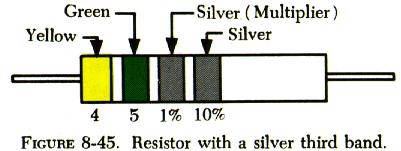
When the third band is silver, as is the case in figure 8-45, the first
two digits must be multiplied by 1 percent. The value of the resistor is
0.45 ± 10 percent ohms.
 Body-End-Dot System
The body-end-dot system of marking is rarely used today. A few examples
will explain it. The location of the colors has the following significance:
Body color...... 1st digit of ohmic value
End color....... 2nd digit of ohmic value
Dot color....... Number of zeros to be added
If only one end of the resistor is painted, it indicates the second
figure of the resistor value, and the tolerance will be 20 percent. The
other two tolerance values are gold (5 percent) and silver (10 percent).
The opposite end of the resistor will be painted to indicate a tolerance
other than 20 percent. Figure 8-46 shows a resistor coded by the body-end-dot
system.
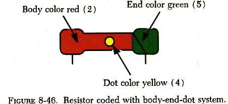
The values are as follows:
Body -- 1st digit -- 2
End -- 2nd digit -- 5
Dot -- No. of zeros -- 0000 (4)
The resistor value is 250,000 ± 20 percent ohms. The tolerance
is understood to be 20 percent because no second dot is used.
If the same color is used more than once, the body, end, and dot may
all be the same color, or any two may be the same; but the color code is
used in exactly the same way. For example, a 33,000 ohm resistor will be
entirely orange.