BASICCIRCUIT2
BASIC CIRCUIT ANALYSIS AND TROUBLESHOOTING
Troubleshooting is the process of locating causes for malfunctions or
trouble in a circuit. The following definitions serve as a guide in the
troubleshooting discussion:
(1) Short circuit - a low resistance path. It can be across the power
source or between the sides of a circuit. It usually creates high current
flow which will burn out or cause damage to the circuit conductor or components.
(2) Open circuit - a circuit that is not complete or continuous.
(3) Continuity - the state of being continuous, or connected together;
said of a circuit that is not broken or does not have an open.
(4) Discontinuity - the opposite of continuity, indicating that a circuit
is broken or not continuous.
Figure 8-141 includes some of the most common
sources of open circuits (commonly called "opens" or "an open"). A loose
connection or no connection is a frequent cause of an open circuit. In
A of figure 8-141, the end of a conductor has separated
from the battery terminal. This type of malfunction opens a circuit and
stops the flow of current. Another type of malfunction that will cause
an open circuit is a burned out resistor, shown in B of figure 8-141. When
a resistor overheats, its resistance value changes; and, if the current
flow through it is great enough, it can burn and open the circuit. In C,
D, and E of figure 8-141, three more likely causes
of open circuits are shown.
| The opens shown can often be located by visual inspection;
however, many circuit opens cannot be seen. In such cases, a meter must
be used.
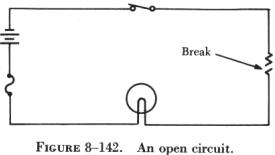
The circuit shown in figure 8-142 is designed to cause current to flow
through a lamp, but because of the open resistor, the lamp will not light.
To locate this open, a voltmeter or an ohmmeter can be used. |
|
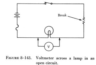 |
If a voltmeter is connected across the lamp, as shown in figure 8-143,
the voltmeter will read zero. Since no current can flow in the circuit
because of the open resistor, there is no voltage drop across the lamp.
This illustrates a troubleshooting rule that should be remembered: When
a voltmeter is connected across a good (not defective) component in an
open circuit, the voltmeter will read zero. |
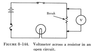
Next, the voltmeter is connected across the open resistor, as shown
in figure 8-144. The voltmeter has closed the circuit by shunting (paralleling)
the burned out resistor, allowing current to flow. Current will flow from
the negative terminal of the battery, through the switch, through the voltmeter
and the lamp, back to the positive terminal of the battery. However, the
resistance of the voltmeter is so high that only a very small current flows
in the circuit.
The current is too small to light the lamp, but the voltmeter will read
the battery voltage. Another troubleshooting point worth remembering is:
When a voltmeter is placed across an open component in a series circuit,
it will read the battery, or applied voltage. |
 |
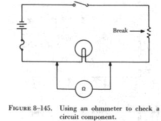 |
This type of open circuit malfunction can also be traced by using an
ohmmeter. When an ohmmeter is used, the circuit component to be tested
must be isolated and the power source removed from the circuit. In this
case, as shown in figure 8-145, these requirements can be met by opening
the circuit switch. The ohmmeter is zeroed and placed across (in parallel
with) the lamp. In this circuit, some value of resistance is read. This
illustrates another important troubleshooting point: when an ohmmeter is
properly connected across a circuit component and a resistance reading
is obtained, the component has continuity and is not open. |
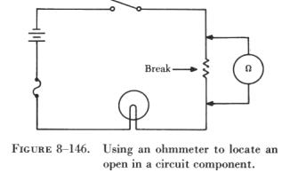
| When the ohmmeter is connected across the open resistor, as shown in
figure 8-146, it indicates infinite resistance, or a discontinuity. Thus,
the circuit open has been located with both a voltmeter and an ohmmeter.
An open in a series circuit will cause the current flow to stop. A short
circuit, or "short," will cause the opposite effect. A short across a series
circuit produces a greater than normal current flow. Some examples of shorts,
as shown in figure 8-147, are two bare wires in
a circuit that are touching each other, two terminals of a resistor connected
together, etc. Thus, a short can be described as a connection of two conductors
of a circuit through a very low resistance. |
|
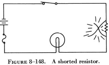 |
In figure 8-148, a circuit is designed to light a lamp. A resistor
is connected in the circuit to limit current flow. If the resistor is shorted,
as shown in the illustration, the current flow will increase and the lamp
will become brighter. If the applied voltage were high enough, the lamp
would burn out, but in this case the fuse would protect the lamp by opening
first. |
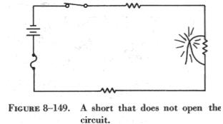
Usually a short circuit will produce an open circuit by either blowing
(opening) the fuse or burning out a circuit component. But in some circuits,
such as that illustrated in figure 8-149, there may be additional resistors
which will not allow one shorted resistor to increase the current flow
enough to blow the fuse or burn out a component. Thus, with one resistor
shorted out, the circuit will still function since the power dissipated
by the other resistors does not exceed the rating of the fuse.
To locate the shorted resistor while the circuit is functioning, a voltmeter
could be used. When it is connected across any of the unshorted resistors,
a portion of the applied voltage will be indicated on the voltmeter scale.
When it is connected across the shorted resistor, the voltmeter will read
zero. |
 |
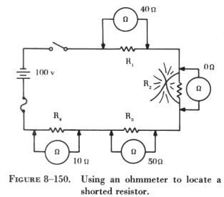 |
The shorted resistor shown in figure 8-150 can be located with an ohmmeter.
First the switch is opened to isolate the circuit components. In figure
8-150, this circuit is shown with an ohmmeter connected across each of
the resistors. Only the ohmmeter connected across the shorted resistor
shows a zero reading, indicating that this resistor is shorted.
The procedures used in troubleshooting a parallel circuit are sometimes
different from those used in a series circuit. Unlike a series circuit,
a parallel circuit has more than one path in which current flows. A voltmeter
cannot be used, since, when it is placed across an open resistor, it will
read the voltage drop in a parallel branch. But an ammeter or the modified
use of an ohmmeter can be employed to detect an open branch in a parallel
circuit. |
If the open resistor shown in figure 8-151 was
not visually apparent, the circuit would appear to be functioning properly,
since current would continue to flow in the other two branches of the circuit.
To determine that the circuit is not operating properly, the total resistance,
total current, and the branch currents of the circuit should be calculated
as if there were no open in the circuit:
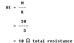
Since the voltage applied to the branches is the same and the value
of each branch resistance is known,
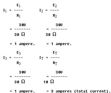
An ammeter placed in the circuit to read total current would show 2
amperes instead of the calculated 3 amperes. Since 1 ampere of current
should be flowing through each branch, it is obvious that one branch is
open. If the ammeter is connected into the branches, one after another,
the open branch will be located by a zero ammeter reading.
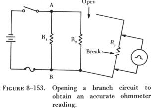
| A modified use of the ohmmeter can also locate this type
of open. If the ohmmeter is connected across the open resistor, as shown
in figure 8-152, an erroneous reading of continuity
would be obtained. Even though the circuit switch is open, the open resistor
is still in parallel with R1 and R2, and the ohmmeter would indicate the
open resistor had a resistance of 15 ohms, the equivalent resistance of
the parallel combination of R1 and R2.
Thus, it is necessary to open the circuit as shown in figure 8-153 in
order to check the resistance of R3. In this way the resistor is not shunted
(paralleled) and the reading on the ohmmeter will indicate infinite resistance.
On the other hand, if an open should occur in this circuit (figure 8-153)
between the battery and point A, or between the battery and point B, current
would not flow in the circuit. |
|
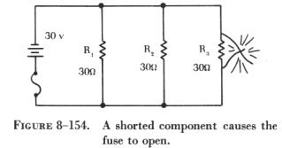 |
As in a series circuit, a short in a parallel circuit will usually
cause an open circuit by blowing the fuse. But, unlike a series circuit,
one shorted component in a parallel circuit will stop current flow by causing
the fuse to open. This can be seen by referring to the circuit in figure
8-154. If resistor R3 is shorted, a path of almost zero resistance will
be offered the current, and all the circuit current will flow through the
branch containing the shorted resistor. Since this is practically the same
as connecting a wire between the terminals of the battery, the current
will rise to an excessive value, and the fuse will open. |
| Since the fuse opens almost as soon as a resistor shorts
out, there is no time to perform a current or voltage check. Thus, troubleshooting
a parallel dc circuit for a shorted component should be accomplished with
an ohmmeter. But, as in the case of checking for an open resistor in a
parallel circuit, a shorted resistor can be detected with an ohmmeter only
if one end of the shorted resistor is disconnected.
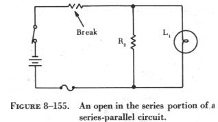
Troubleshooting a series-parallel resistive circuit involves locating
malfunctions similar to those found in a series or a parallel circuit.
In the circuit shown in figure 8-155, an open has occurred in the series
portion of the circuit. When an open occurs anywhere in the series portion
of a series-parallel circuit, current flow in the entire circuit will stop.
In this case, the circuit will not function, and the lamp, L1, will not
be lit. |
|
If an open occurs in the parallel portion of a series-parallel circuit,
as shown in figure 8-156, part of the circuit will
continue to function. In this case, the lamp will continue to burn, but
its brightness will diminish, since the total resistance of the circuit
has increased and the total current has decreased.
If a break occurs in the branch containing the lamp, as shown in figure
8-157, the circuit will continue to function with increased resistance
and decreased current, but the lamp will not burn.
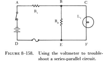 |
To explain how the voltmeter and ohmmeter can be used to troubleshoot
series-parallel circuits, the circuit shown in figure 8-158 has been labeled
at various points. By connecting a voltmeter between points A and D, the
battery and switch can be checked for opens. By connecting the voltmeter
between points A and B, the voltage drop across R1 can be checked. This
voltage drop is a portion of the applied voltage. Also, if R1 is open,
the reading between B and D will be zero. The conductor between the positive
terminal of the battery and point E, as well as the fuse, can be checked
for continuity by connecting the voltmeter between points A and E. If the
conductor or fuse is open, the voltmeter will read zero. |
If the lamp is burning, it is obvious that no open exists in the branch
containing the lamp, and the voltmeter could be used to detect an open
in the branch containing R2 by removing lamp, L1, from the circuit.
Troubleshooting the series portion of a series-parallel circuit presents
no difficulties, but in the parallel portion of the circuit misleading
readings can be obtained.
An ohmmeter can be used to troubleshoot this same circuit. With the
switch open, the series portion of the circuit can be checked by placing
the ohmmeter leads between points A and B. If R1 or the conductor is open,
the ohmmeter will read infinity; if not, the value of the resistor will
be indicated on the ohmmeter. Between points D and E the fuse and conductor
can be checked for continuity, but in the parallel portion of the circuit,
care must be exercised, since misleading ohmmeter indications can be obtained.
To check between points B and E, the branch must be disconnected at one
of these points, and while one of these points and the switch are open,
the branch containing the lamp can be cheeked with the ohmmeter.
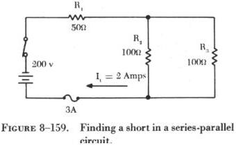
| A short in the series part of a series-parallel circuit
will cause a decrease in total resistance, which will cause total current
to increase. In the circuit shown in figure 8-159, the total resistance
is 100 ohms and the total current is 2 amperes. If R1 became shorted, total
resistance would become 50 ohms, and the total current would double to
4 amperes. In the circuit shown, this would cause the 3 amp fuse to blow,
but with a 5 amp fuse the circuit would continue to function.
The result would be the same if R2 or R3 were to become shorted. The
total resistance in either case would drop to 50 ohms. From this, it can
be stated that when a short occurs in a series-parallel circuit, the total
resistance will decrease and the total current will increase. A short will
normally cause an open circuit by either blowing the fuse or burning out
a circuit component. And, as in the case of an open, a short in a series-parallel
circuit can be detected with either an ohmmeter or a voltmeter. |
|