Another important property in ac circuits, besides resistance and inductance, is capacitance. While inductance is represented in a circuit by a coil, capacitance is represented by a capacitor.
Any two conductors separated by a nonconductor, called a dielectric,
constitute a capacitor. In an electrical circuit, a capacitor serves as
a reservoir or storehouse for electricity.
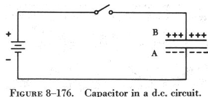
| When a capacitor is connected across a source of direct current, such as a storage battery in the circuit shown in figure 8-176, and the switch is then closed, the plate marked B becomes positively charged, and the A plate negatively charged. Current flows in the external circuit during the time the electrons are moving from B to A. The current flow in the circuit is maximum the instant the switch is closed, but continually decreases thereafter until it reaches zero. The current becomes zero as soon as the difference in voltage of A and B becomes the same as the voltage of the battery. If the switch is opened, the plates remain charged. However, the capacitor quickly discharges when it is short circuited. |
|
The amount of electricity a capacitor can store depends on several factors, including the type of material of the dielectric. It is directly proportional to the plate area and inversely proportional to the distance between the plates.
In figure 8-177, two flat metal plates are placed close to each other (but not touching). Usually the plates are electrically neutral; that is, no electrical charge will be evident on either plate. At the instant the switch is closed to the battery position, the meter will show a definite current surge in one direction, but almost instantly will return to zero.
If the battery is then taken out of the circuit and the switch closed in the capacitor position, the meter again shows a momentary current surge, but this time in an opposite direction. From this experiment it is apparent that the two plates store energy when connected to a voltage source, and release the energy when short circuited. The two plates make up a simple electrical capacitor, or condenser, and possess the property of storing electricity. The energy is actually stored in the electric, or dielectric, field between the plates.
Also, it should be clear that during the time the capacitor is being charged or discharged there is current in the circuit, even though the circuit is broken by the gap between the capacitor plates. However, there is current only during the time of charge and discharge, and this period of time is very short. There can be no continuous movement of direct current through a capacitor. A good capacitor will block direct current (not pulsating dc) and will pass the effects of alternating current.
The charge of electricity that can be placed on a capacitor is proportional to the applied voltage and to the capacitance of the capacitor (condenser). Capacitance depends upon the total area of the plates, the thickness of the dielectric and the composition of the dielectric.
If a thin sheet of bakelite (mica filled) is substituted for air between the plates of a capacitor, for example, the capacitance will be increased about five times.
Any electric charge produced by applied voltage and kept in bounds by
an insulator (dielectric) creates a dielectric field. Once the field is
created, it tends to oppose any voltage change which would affect its original
position. All circuits contain some capacitance, but unless they contain
a unit called a capacitor, the capacitance, for all practical purposes,
is disregarded. Two conductors, called electrodes or plates, separated
by a nonconductor (dielectric) make up a simple capacitor. The plates may
be made of copper, tin, or aluminum. Frequently, they are made of foil
(metals compressed into thin sheets and capable of being rolled). The dielectric
may be air, glass, mica, or an electrolyte made by an oxide film, but the
type used will determine the amount of voltage that may be applied and
the quantity of energy that will be stored. The dielectric materials have
different atomic structures and present different quantities of atoms to
the electrostatic field. All dielectric materials are compared to a vacuum
and are given a numerical value according to the capacity ratio between
them. The number given to a material is based on the same area and thickness
as used in the vacuum. The numbers used to express this ratio are called
dielectric constants and are expressed as the letter "K."
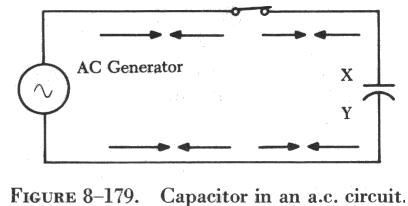
| If a source of alternating current is substituted for the battery, the capacitor acts quite differently than it does with direct current. When an alternating current is impressed on the circuit (figure 8-179), the charge on the plates constantly changes. This means that electricity must flow first from Y clockwise around to X, then from X counterclockwise around to Y, then from Y clockwise around to X, and so on. Although no current flows through the insulator between the plates of the capacitor, it constantly flows in the remainder of the circuit between X and Y. In a circuit in which there is only capacitance, current leads the impressed voltage as contrasted with a circuit in which there is inductance, where the current lags the voltage. |
 |
The unit of measurement of capacitance is the farad, for which the symbol
is the letter "f" The farad is too large for practical use, and the units
generally used are the microfarad ![]() ,
one millionth of a farad, and the micromicrofarad
,
one millionth of a farad, and the micromicrofarad ![]() ,
one millionth of a microfarad.
,
one millionth of a microfarad.
Types of Capacitors
Capacitors may be divided into two groups: fixed and variable. The fixed capacitors, which have approximately constant capacitance, may then be further divided, according to the type of dielectric used, into the following classes: paper, oil, mica, and electrolytic capacitors. Ceramic capacitors are also used in some circuits.
When connecting electrolytic capacitors in a circuit, the proper polarity must be observed. Paper capacitors may have one terminal marked "ground," which means that this terminal connects to the outside foil. Polarity does not ordinarily have to be observed in connecting paper, oil, mica, or ceramic capacitors.
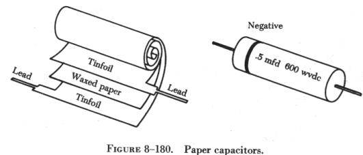
Paper Capacitors
The plates of paper capacitors are strips of metal foil separated by
waxed paper (figure 8-180). The capacitance of paper capacitors ranges
from about 200 mmf to several mf. The strips of foil and paper are rolled
together to form a cylindrical cartridge, which is then sealed in wax to
keep out moisture and to prevent corrosion and leakage. Two metal leads
are soldered to the plates, one extending from each end of the cylinder.
The assembly is enclosed either in a cardboard cover or in a hard, molded
plastic covering.
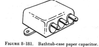
| Bathtub-type capacitors consist of paper capacitor cartridges hermetically sealed in metal containers. The container often serves as a common terminal for several enclosed capacitors, but when not a terminal, the cover serves as a shield against electrical interference (figure 8-181). |
 |
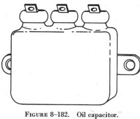 |
Oil Capacitors
In radio and radar transmitters, voltages high enough to cause arcing, or breakdown, of paper dielectrics are often employed. Consequently, in these applications capacitors that use oil or oil impregnated paper for the dielectric material are preferred. Capacitors of this type are considerably more expensive than ordinary paper capacitors, and their use is generally restricted to radio and radar transmitting equipment (figure 8-182). |
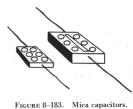
| Mica Capacitors
The fixed mica capacitor is made of metal foil plates that are separated by sheets of mica, which form the dielectric. The whole assembly is covered in molded plastic, which keeps out moisture. Mica is an excellent dielectric and will withstand higher voltages than paper without allowing arcing between the plates. Common values of mica capacitors range from approximately 50 micromicrofarads, to about 0.02 microfarads. Mica capacitors are shown in figure 8-183. Electrolytic Capacitors For capacitances greater than a few microfarads, the plate areas of paper or mica capacitors must become very large; thus, electrolytic capacitors are usually employed instead. These units provide large capacitance in small physical sizes. Their values range from 1 to about 1,500 microfarads. Unlike the other types, electrolytic capacitors are generally polarized, and should be subjected to direct voltage, or pulsating direct voltage only; however, a special type of electrolytic capacitor is made for use in motors. |
 |
The electrolytic capacitor is widely used in electronic circuits and consists of two metal plates separated by an electrolyte. The electrolyte in contact with the negative terminal, either in paste or liquid form, comprises the negative electrode. The dielectric is an exceedingly thin film of oxide deposited on the positive electrode of the capacitor. The positive electrode, which is an aluminum sheet, is folded to achieve maximum area. The capacitor is subjected to a forming process during manufacture, in which current is passed through it. The flow of current results in the deposit of the thin coating of oxide on the aluminum plate.
The close spacing of the negative and positive electrodes gives rise to the comparatively high capacitance value, but allows greater possibility of voltage breakdown and leakage of electrons from one electrode to the other.
Two kinds of electrolytic capacitors are in use: (1) Wet electrolytic and (2) dry electrolytic capacitors. In the former, the electrolyte is a liquid and the container must be leakproof. This type should always be mounted in a vertical position.
The electrolyte of the dry electrolytic unit is a paste contained in a separator made of an absorbent material such as gauze or paper. The separator not only holds the electrolyte in place but also prevents short circuiting the plates. Dry electrolytic capacitors are made in both cylindrical and rectangular block form and may be contained either within cardboard or metal covers. Since the electrolyte cannot spill, the dry capacitor may be mounted in any convenient position. Electrolytic capacitors are shown in figure 8-184.
Capacitors in Parallel and in Series
Capacitors may be combined in parallel or series to give equivalent values, which may be either the sum of the individual values (in parallel) or a value less than that of the smallest capacitance (in series). Figure 8-185 shows the parallel and series connections.
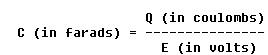
Two units used in the measurement of capacitance are the farad and the coulomb. As previously defined, the farad is the amount of capacitance present in a capacitor when one coulomb of electrical energy is stored on the plates and one volt is applied across the capacitor. One coulomb is the electrical charge of 6.28 billion billion electrons. From this it can be seen that
In A of figure 8-185 the voltage, E, is the same for all the capacitors. The total charge, Qt, is the sum of all the individual charges, Q1, Q2, and Q3.
Using the basic equation for the capacitor,

The total charge is Qt = CtE, where Ct is the total capacitance. Since the total charge on capacitors in parallel is the sum of the individual capacitor charges,
Qt = Q1 + Q2 + Q3.
Using both equations for total charge develops the equation
CtE = C1E + C2E + C3E.
Dividing both sides of this equation by E gives
Ct = C1 + C2 + C3.
This formula is used to determine the total capacitance of any number
of capacitors in parallel. In the series arrangement, (B of figure
8-185), the current is the same in all parts of the circuit. Each capacitor
develops a voltage during charge, and the sum of the voltages of all the
capacitors must equal the applied voltage, E. By the capacitor equation,
the applied voltage, E, is equal to the total charge divided by the total
capacitance, or
The total charge, Qt, is equal to the charge on any one of the capacitors because the same current flows in all for the same length of time, and because the charge equals current multiplied by time in seconds (Qt = I x T). Therefore,
Qt = Q1 = Q2 = Q3,
and, since in a circuit with capacitors in series
Et = E1 + E2 + E3,
where E1, E2, and E3 are the voltages of the three capacitors. Then
![]()
Dividing both sides of the equation by Qt gives
![]()
The reciprocal of the total capacitance of any number of capacitors in series is equal to the sum of the reciprocals of the individual values.
Parallel capacitors combine by a rule similar to that used to combine resistors in series. Series capacitors combine by a rule similar to that for combining parallel resistors.
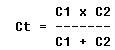
In the series arrangement of two capacitors, C1 and C2, the total capacitance is given by the equation:
Voltage Rating of Capacitors
In selecting or substituting a capacitor for use in a particular circuit, the following must be considered: (1) The value of capacitance desired and (2) the amount of voltage to which the capacitor is to be subjected. If the voltage applied across the plates is too great, the dielectric will break down and arcing will occur between the plates. The capacitor is then short circuited, and the possible flow of direct current through it can cause damage to other parts of the equipment. Capacitors have a voltage rating that should not be exceeded.
The working voltage of the capacitor is the maximum voltage that can be steadily applied without danger of arc over. The working voltage depends on (1) the type of material used as the dielectric and (2) the thickness of the dielectric.
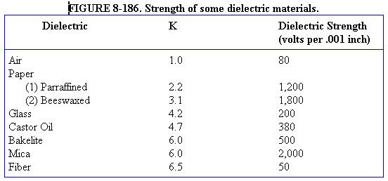
The voltage rating of the capacitor is a factor in determining the capacitance because capacitance decreases as the thickness of the dielectric increases. A high voltage capacitor that has a thick dielectric must have a larger plate area in order to have the same capacitance as a similar low voltage capacitor having a thin dielectric. The strength of some commonly used dielectric materials is listed in figure 8-186. The voltage rating also depends on frequency because the losses, and the resultant heating effect, increase as the frequency increases.
A capacitor that can be safely charged to 500 volts dc cannot be safely subjected to ac or pulsating dc whose effective values are 500 volts. An alternating voltage of 500 volts (r.m.s.) has a peak voltage of 707 volts, and a capacitor to which it is applied should have a working voltage of at least 750 volts. The capacitor should be selected so that its working voltage is at least 50 percent greater than the highest voltage to be applied to it.
Capacitance Reactance
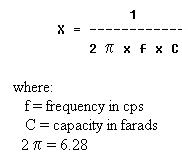
Capacitance, like inductance, offers opposition to the flow of current. This opposition is called capacitive reactance and is measured in ohms. The symbol for capacitive reactance is Xc. The equation,
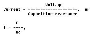
is similar to Ohm's law and the equation for current in an inductive circuit. The greater the frequency, the less the reactance. Hence, the capacitive reactance,
Problem:
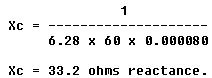
A series circuit is assumed in which the impressed voltage is 110 volts
at 60 cps, and the capacitance of a condenser is 80 ![]() .
Find the capacitive reactance and the current flow.
.
Find the capacitive reactance and the current flow.
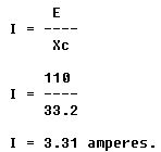
Solution:
To find capacitive reactance, the equation ![]() is changed to farads by dividing 80 by 1,000,000, since 1 million microfarads
is equal to 1 farad. This quotient equals 0.000080 farad. This is substituted
in the equation and
is changed to farads by dividing 80 by 1,000,000, since 1 million microfarads
is equal to 1 farad. This quotient equals 0.000080 farad. This is substituted
in the equation and
Find the current flow: =
Capacitive Reactances in Series and in Parallel
When capacitors are connected in series, the total reactance is equal to the sum of the individual reactances. Thus,
Xct = (Xc)1 + (Xc)2
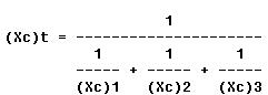
The total reactance of capacitors connected in parallel is found in
the same way total resistance is computed in a parallel circuit:
Phase of Current and Voltage in Reactive Circuits
When current and voltage pass through zero and reach maximum value at the same time, the current and voltage are said to be in phase (A of figure 8-187). If the current and voltage pass through zero and reach the maximum values at different times, the current and voltage are said to be out of phase. In a circuit containing only inductance, the current reaches a maximum value later than the voltage, lagging the voltage by 90°, or one-fourth cycle (B of figure 8-187). In a circuit containing only capacitance, the current reaches its maximum value ahead of the voltage and the current leads the voltage by 90°, or one-fourth cycle (C of figure 8-187). The amount the current lags or leads the voltage in a circuit depends on the relative amounts of resistance, inductance, and capacitance in the circuit.