Many aircraft, especially aircraft of more than 12,500 pounds, employ both a dc and an ac electrical system. Often the dc system is the basic electrical system and consists of paralleled dc generators with output of, for example, 300 amperes each.
The ac system on such aircraft may include both a fixed frequency and a variable frequency system. The fixed frequency system may consist of three or four inverters and associated controls, protective, and indicating components to provide single phase, ac power for frequency sensitive ac equipment. The variable frequency system may consist of two or more engine driven alternators, with associated control, protective, and indicating components, to provide three phase, ac power for such purposes as resistive heating on propellers, engine ducts, and windshields.
Such combined dc and ac electrical systems normally include an auxiliary source of dc power to back up the main system. This generator is often driven by a separate gasoline or turbine powered unit.
Alternator Rating
The maximum current that can be supplied by an alternator depends upon the maximum heating loss (I^2R power loss) that can be sustained in the armature and the maximum heating loss that can be sustained in the field. The armature current of an alternator varies with the load. This action is similar to that of dc generators. In ac generators, however, lagging power factor loads tend to demagnetize the field of an alternator and terminal voltage is maintained only by increasing dc field current. For this reason, alternating current generators are usually rated according to KVA, power factor, phases, voltage, and frequency. One generator, for example, may be rated at 40 KVA, 208 volts, 400 cycles, three phase, at 75 percent power factor. The KVA indicate the apparent power. This is the KVA output, or the relationship between the current and voltage at which the generator is intended to operate.
The power factor is the expression of the ratio between the apparent power (volt-amperes) and the true or effective power (watts). The number of phases is the number of independent voltages generated. Three phase generators generate three voltages 120 electrical degrees apart.
Alternator Frequency
The frequency of the alternator voltage depends upon the speed of rotation of the rotor and the number of poles. The faster the speed, the higher the frequency will be; the lower the speed, the lower the frequency becomes. The more poles on the rotor, the higher the frequency will be for a given speed. When a rotor has rotated through an angle so that two adjacent rotor poles (a north and a south pole) have passed one winding, the voltage induced in that winding will have varied through one complete cycle. For a given frequency, the greater the number of pairs of poles, the lower the speed of rotation will be. A two pole alternator rotates at twice the speed of a four pole alternator for the same frequency of generated voltage. The frequency of the alternator in cps is related to the number of poles and the speed, as expressed by the equation
![]()
where P is the number of poles and N the speed in rpm. For example, a two pole, 3,600 rpm.
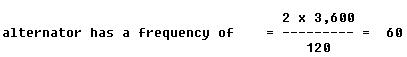
cps; a four pole, 1,800 rpm alternator has the same frequency; a six pole, 500 rpm alternator
![]()
12 pole, 4,000 rpm alternator has a frequency of
![]()