Cables are the most widely used linkage in primary flight control systems. Cable-type linkage is also used in engine controls, emergency extension systems for the landing gear, and various other systems throughout the aircraft.
Cable-type linkage has several advantages over the other types. It is strong and light in weight, and its flexibility makes it easy to route through the aircraft. An aircraft cable has a high mechanical efficiency and can be set up without backlash, which is very important for precise control.
Cable linkage also has some disadvantages. Tension must be adjusted frequently due to stretching and temperature changes.
Aircraft control cables are fabricated from carbon steel or stainless steel.
Cable Construction
The basic component of a cable is a wire. The diameter of the wire determines the total diameter of the cable. A number of wires are preformed into a helical or spiral shape and then formed into a strand. These preformed strands are laid around a straight center strand to form a cable.
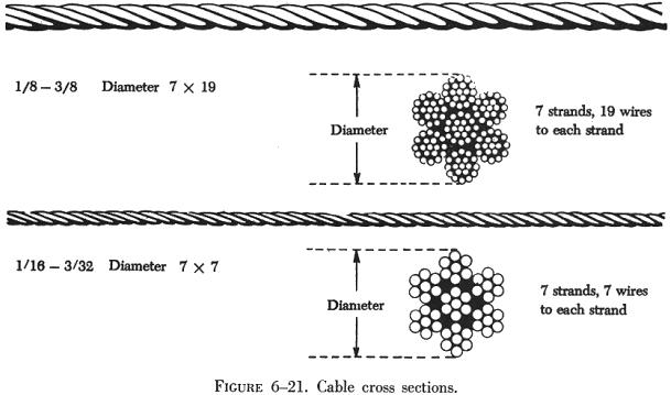
Cable designations are based on the number of strands and the number of wires in each strand. The most common aircraft cables are the 7 x 7 and 7 x 19.
The 7 x 7 cable consists of seven strands of seven wires each. Six of these strands are laid around the center strand (see figure 6-21).This is a cable of medium flexibility and is used for trim tab controls, engine controls, and indicator controls.
The 7 x 19 cable is made up of seven strands of 19 wires each. Six of these strands are laid around the center strand (see figure 6-21). This cable is extra flexible and is used in primary control systems and in other places where operation over pulleys is frequent. Aircraft control cables vary in diameter, ranging from 1/16 to 3/8 inch. The diameter is measured as shown in figure 6-21.
Cable Fittings
Cables may be equipped with several different types of fittings such as terminals, thimbles, bushings, and shackles.
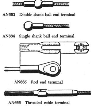
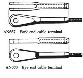
Terminal fittings are generally of the swaged type. They are available
in the threaded end, fork end, eye end, single shank ball end, and double
shank ball end. The threaded end, fork end, and eye end terminals are used
to connect the cable to a turnbuckle, bellcrank, or other linkage in the
system. The ball end terminals are used for attaching cables to quadrants
and special connections where space is limited. Figure 6-22 illustrates
the various types of terminal fittings.
 |
 |
The thimble, bushing, and shackle fittings may be used in place of some types of terminal fittings when facilities and supplies are limited and immediate replacement of the cable is necessary.
Turnbuckles
A turnbuckle assembly is a mechanical screw device consisting of two threaded terminals and a threaded barrel. Figure 6-23 illustrates a typical turnbuckle assembly.
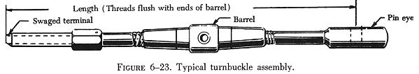
Turnbuckles are fitted in the cable assembly for the purpose of making minor adjustments in cable length and for adjusting cable tension. One of the terminals has right-hand threads and the other has left-hand threads. The barrel has matching right and left-hand internal threads. The end of the barrel with the left-hand threads can usually be identified by a groove or knurl around that end of the barrel.
When installing a turnbuckle in a control system, it is necessary to screw both of the terminals an equal number of turns into the barrel. It is also essential that all turnbuckle terminals be screwed into the barrel until not more than three threads are exposed on either side of the turnbuckle barrel.
After a turnbuckle is properly adjusted, it must be safetied. The methods
of safetying turnbuckles are discussed later in this chapter.