DCGENERATORS
DC GENERATORS
Energy for the operation of most electrical equipment in an airplane
depends upon the electrical energy supplied by a generator. A generator
is any machine which converts mechanical energy into electrical energy
by electromagnetic induction. A generator designed to produce alternating
current energy is called an ac generator, or alternator; a generator which
produces direct current energy is called a dc generator. Both types operate
by inducing an ac voltage in coils by varying the amount and direction
of the magnetic flux cutting through the coils.
For airplanes equipped with direct current electrical systems, the dc
generator is the regular source of electrical energy. One or more dc generators,
driven by the engine, supply electrical energy for the operation of all
units in the electrical system, as well as energy for charging the battery.
The number of generators used is determined by the power requirement of
a particular airplane. In most cases, only one generator is driven by each
engine, but in some large airplanes, two generators are driven by a single
engine. Aircraft equipped with alternating current systems use electrical
energy supplied by ac generators, also called alternators.
Theory of Operation
| In the study of alternating current, basic generator principles
were introduced to explain the generation of an ac voltage by a coil rotating
in a magnetic field. Since this is the basis for all generator operation,
it is necessary to review the principles of generation of electrical energy.
When lines of magnetic force are cut by a conductor passing through
them, voltage is induced in the conductor. The strength of the induced
voltage is dependent upon the speed of the conductor and the strength of
the magnetic field. If the ends of the conductor are connected to form
a complete circuit, a current is induced in the conductor. The conductor
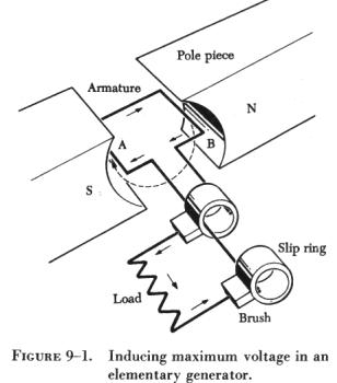
and the magnetic field make up an elementary generator. This simple generator
is illustrated in figure 9-1, together with the components of an external
generator circuit which collect and use the energy produced by the simple
generator. The loop of wire (A and B of figure 9-1) is arranged to rotate
in a magnetic field. When the plane of the loop of wire is parallel to
the magnetic lines of force, the voltage induced in the loop causes a current
to flow in the direction indicated by the arrows in figure 9-1. The voltage
induced at this position is maximum, since the wires are cutting the lines
of force at right angles and are thus cutting more lines of force per second
than in any other position relative to the magnetic field. |
|
As the loop approaches the vertical position shown in figure
9-2, the induced voltage decreases because both sides of the loop (A
and B) are approximately parallel to the lines of force and the rate of
cutting is reduced.
When the loop is vertical, no lines of force are cut since the wires
are momentarily traveling parallel to the magnetic lines of force, and
there is no induced voltage. As the rotation of the loop continues, the
number of lines of force cut increases until the loop has rotated an additional
90° to a horizontal plane. As shown in figure 9-3,
the number of lines of force cut and the induced voltage once again are
maximum. The direction of cutting, however, is in the opposite direction
to that occurring in figure 9-1 and figure 9-2, so
the direction (polarity) of the induced voltage is reversed.
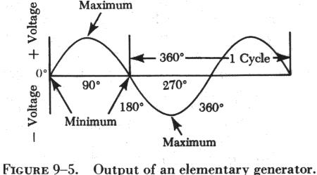
| As rotation of the loop continues, the number of lines
of force having been cut again decreases, and the induced voltage becomes
zero at the position shown in figure 9-4, since the
wires A and B are again parallel to the magnetic lines of force. If the
voltage induced throughout the entire 360° of rotation is plotted,
the curve shown in figure 9-5 results. This voltage is called an alternating
voltage because of its reversal from positive to negative values - first
in one direction and then in the other. |
|
To use the voltage generated in the loop for producing a current flow
in an external circuit, some means must be provided to connect the loop
of wire in series with the external circuit. Such an electrical connection
can be effected by opening the loop of wire and connecting its two ends
to two metal rings, called slip rings, against which two metal or carbon
brushes ride. The brushes are connected to the external circuit.
By replacing the slip rings of the basic ac generator with two half
cylinders, called a commutator, a basic dc generator (figure
9-6), is obtained. In this illustration the black side of the coil
is connected to the black segment and the white side of the coil to the
white segment. The segments are insulated from each other. The two stationary
brushes are placed on opposite sides of the commutator and are so mounted
that each brush contacts each segment of the commutator as the latter revolves
simultaneously with the loop. The rotating parts of a dc generator (coil
and commutator) are called an armature.
The generation of an e.m.f. by the loop rotating in the magnetic field
is the same for both ac and dc generators, but the action of the commutator
produces a dc voltage.
This generation of a dc voltage is described as follows for the various
positions of the loop rotating in a magnetic field, with reference to figure
9-7. The loop in position A of figure 9-7 is rotating clockwise, but
no lines of force are cut by the coil sides and no e.m.f. is generated.
The black brush is shown coming into contact with the black segment of
the commutator, and the white brush is just coming into contact with the
white segment.
In position B of figure 9-7, the flux is being
cut at a maximum rate and the induced e.m.f. is maximum. At this time,
the black brush is contacting the black segment and the white brush is
contacting the white segment. The deflection of the meter is toward the
right, indicating the polarity of the output voltage.
At position C of figure 9-7, the loop has completed
180° of rotation. Again, no flux lines are being cut and the output
voltage is zero. The important condition to observe at position C is the
action of the segments and brushes. The black brush at the 180° angle
is contacting both black and white segments on one side of the commutator,
and the white brush is contacting both segments on the other side of the
commutator. After the loop rotates slightly past the 180° point, the
black brush is contacting only the white segment and the white brush is
contacting only the black segment.
Because of this switching of commutator elements, the black brush is
always in contact with the coil side moving downward, and the white brush
is always in contact with the coil side moving upward. Though the current
actually reverses its direction in the loop in exactly the same way as
in the ac generator, commutator action causes the current to flow always
in the same direction through the external circuit or meter.
A graph of one cycle of operation is shown in figure
9-7. The generation of the e.m.f. for positions A, B, and C is the
same as for the basic ac generator, but at position D, commutator action
reverses the current in the external circuit, and the second half cycle
has the same waveform as the first half cycle. The process of commutation
is sometimes called rectification, since rectification is the converting
of an ac voltage to a dc voltage.
At the instant that each brush is contacting two segments on the commutator
(positions A, C, and E in figure 9-7), a direct short
circuit is produced. If an e.m.f. were generated in the loop at this time,
a high current would flow in the circuit, causing an arc and thus damaging
the commutator. For this reason, the brushes must be placed in the exact
position where the short will occur when the generated e.m.f. is zero.
This position is called the neutral plane.
The voltage generated by the basic dc generator in figure
9-7 varies from zero to its maximum value twice for each revolution
of the loop. This variation of dc voltage is called "ripple," and may be
reduced by using more loops, or coils, as shown in A of figure 9-8.
As the number of loops is increased, the variation between maximum and
minimum values of voltage is reduced (B of figure 9-8),
and the output voltage of the generator approaches a steady dc value. In
A of figure 9-8 the number of commutator segments
is increased in direct proportion to the number of loops; that is, there
are two segments for one loop, four segments for two loops, and eight segments
for four loops.
The voltage induced in a single turn loop is small. Increasing the number
of loops does not increase the maximum value of generated voltage, but
increasing the number of turns in each loop will increase this value. Within
narrow limits, the output voltage of a dc generator is determined by the
product of the number of turns per loop, the total flux per pair of poles
in the machine, and the speed of rotation of the armature.
An ac generator, or alternator, and a dc generator are identical as
far as the method of generating voltage in the rotating loop is concerned.
However, if the current is taken from the loop by slip rings, it is an
alternating current, and the generator is called an ac generator, or alternator.
If the current is collected by a commutator, it is direct current, and
the generator is called a dc generator.
Construction Features of DC Generators
Generators used on aircraft may differ somewhat in design, since they
are made by various manufacturers. All, however, are of the same general
construction and operate similarly. The major parts, or assemblies, of
a dc generator are a field frame (or yoke), a rotating armature, and a
brush assembly. The parts of a typical aircraft generator are shown in
figure 9-9.
Field Frame
The field frame is also called the yoke, which is the foundation or
frame for the generator. The frame has two functions: It completes the
magnetic circuit between the poles and acts as a mechanical support for
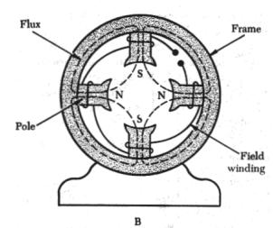
the other parts of the generator. In A of figure 9-10, the frame for a
two pole generator is shown in a cross-sectional view. A four pole generator
frame is shown in B of figure 9-10.
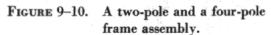
In small generators, the frame is made of one piece of iron, but in
larger generators, it is usually made up of two parts bolted together.
The frame has high magnetic properties and, together with the pole pieces,
forms the major part of the magnetic circuit. The field poles, shown in
figure 9-10, are bolted to the inside of the frame and form a core on which
the field coil windings are mounted.
The poles are usually laminated to reduce eddy current losses and serve
the same purpose as the iron core of an electromagnet; that is, they concentrate
the lines of force produced by the field coils. The entire frame including
field poles, is made from high quality magnetic iron or sheet steel.
| A practical dc generator uses electromagnets instead of
permanent magnets. To produce a magnetic field of the necessary strength
with permanent magnets would greatly increase the physical size of the
generator.
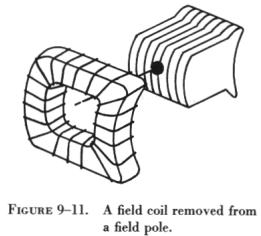
The field coils are made up of many turns of insulated wire and are
usually wound on a form which fits over the iron core of the pole to which
it is securely fastened (figure 9-11). The exciting current, which is used
to produce the magnetic field and which flows through the field coils,
is obtained from an external source or from the generated dc of the machine.
No electrical connection exists between the windings of the field coils
and the pole pieces.
Most field coils are connected in such a manner that the poles show
alternate polarity. Since there is always one north pole for each south
pole, there must always be an even number of poles in any generator. |
|
Note that the pole pieces in figure 9-10 project
from the frame. Because air offers a great amount of reluctance to the
magnetic field, this design reduces the length of the air gap between the
poles and the rotating armature and increases the efficiency of the generator.
When the pole pieces are made to project as shown in figure
9-10, they are called salient poles.
Armature
The armature assembly consists of armature coils wound on an iron core,
a commutator, and associated mechanical parts. Mounted on a shaft, it rotates
through the magnetic field produced by the field coils. The core of the
armature acts as an iron conductor in the magnetic field and, for this
reason, is laminated to prevent the circulation of eddy currents.
There are two general kinds of armatures: the ring and the drum. Figure
9-12 shows a ring-type armature made up of an iron core, an eight section
winding, and an eight segment commutator. This kind of armature is rarely
used; most generators use the drum-type armature.
A drum-type armature (figure 9-13) has coils
placed in slots in the core, but there is no electrical connection between
the coils and core. The use of slots increases the mechanical safety of
the armature. Usually, the coils are held in place in the slots by means
of wooden or fiber wedges. The connections of the individual coils, called
coil ends, are brought out to individual segments on the commutator.
Commutators
Figure 9-14 shows a cross-sectional view of a
typical commutator. The commutator is located at the end of an armature
and consists of wedge shaped segments of hard drawn copper, insulated from
each other by thin sheets of mica. The segments are held in place by steel
V-rings or clamping flanges fitted with bolts. Rings of mica insulate the
segments from the flanges. The raised portion of each segment is called
a riser, and the leads from the armature coils are soldered to the risers.
When the segments have no risers, the leads are soldered to short slits
in the ends of the segments.
The brushes ride on the surface of the commutator, forming the electrical
contact between the armature coils and the external circuit. A flexible,
braided copper conductor, commonly called a pigtail, connects each brush
to the external circuit. The brushes, usually made of high grade carbon
and held in place by brush holders insulated from the frame, are free to
slide up and down in their holders in order to follow any irregularities
in the surface of the commutator. The brushes are usually adjustable so
that the pressure of the brushes on the commutator can be varied and the
position of the brushes with respect to the segments can be adjusted.
The constant making and breaking of connections to the coils in which
a voltage is being induced necessitates the use of material for brushes
which has a definite contact resistance. Also, this material must be such
that the friction between the commutator and the brush is low, to prevent
excessive wear. For these reasons, the material commonly used for brushes
is high grade carbon. The carbon must be soft enough to prevent undue wear
of the commutator and yet hard enough to provide reasonable brush life.
Since the contact resistance of carbon is fairly high, the brush must be
quite large to provide a large area of contact. The commutator surface
is highly polished to reduce friction as much as possible. Oil or grease
must never be used on a commutator, and extreme care must be used when
cleaning it to avoid marring or scratching the surface.